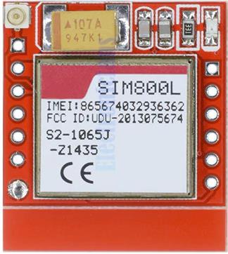
In the previous artiсle I have considered in detail the relatively expensive (color of the sea wave :-)) GSM module SIM800C and its connection to microcontrollers ESP32/ESP8266 series. I didn’t like this GSM module SIM800C. In my opinion there is no any sense to overpay for this module, it is better to take the inexpensive “red” module SIM800C/L and a little bit improve it, adding in the schematic additional elements:
- Resistive divider for RX module input for TTL level matching. The calculation of the resistive divider is reviewed in the previous article.
- DC-DC step down converter. The scheme is used inexpensive module Mini-360 for $0.3.
- Several capacitors for filtering pulsations of the DC-DC step-down converter.
At least this module gets into the solderless mounting board without any problems, as the distance between the pin rows multiple 2.54 mm. The nuances of working with SIM800 are described in detail in the previous article.
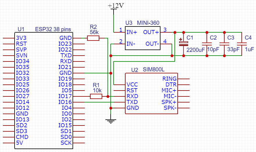
Schematic of the connection SIM800L to ESP32
I use SIM800L for developing quite expensive equipment that should work guaranteed. Therefore I add capacitors according to the recommendations of the datasheet.
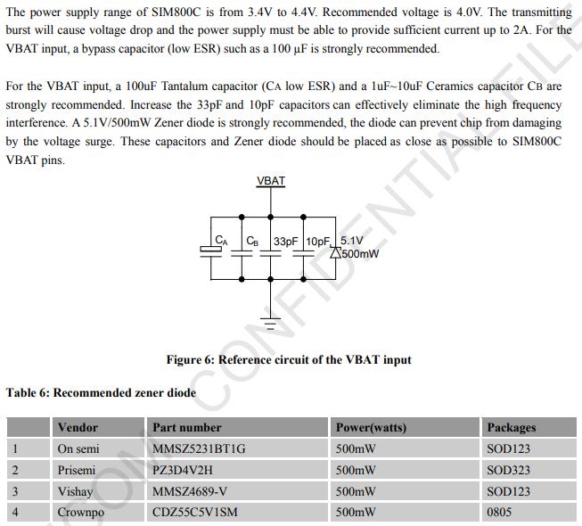
The tantalum capacitor on the “red” SIM800 module has already soldered. I have added 2200 mF electrolytic capacitor and others capacitors according to the datasheet.
The ESP32 microcontroller in this example powered from the USB port of the PC.
Since one UART port is used for data transfer and the second is for receiving, you can use a resistive divider instead of a TTL level converter. But there is one risk involved in this case. If the programmer mixes up the TX and RX pins during the initialization of the serial port, he can burn the TX800 port of SIM800. Therefore, in case of such economy, it is necessary to code very carefully. 🙂
If you do the conversion of levels professionally, then you need to use the TTL level converter, supplied by the microcontroller voltage 3,3V from one side and SIM800L reference voltage getting from the chain resistor and Zener diod for another side. The calculation is here. Zener diod 2.7 V – 3 V.
The datasheet module specifies the maximum level of the logical 1 of RX input – 3.1 B (with a minimum of 2.1 V). Accordingly, 2.7 V will be enough, and 3V is already risky. If you look at the datasheet reference voltage SIM800L: 2.7V – 2.9V.
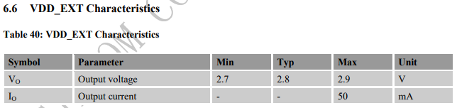
The minimum value is 2.7 V as Zener diod supply. I just say that I use a simple schematic with resistive divider.
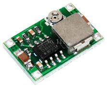
Mini-360 DC-DC Converter is not the best option. It normally withstands the load, SIM800L loaded with it stably, but the quality of the variable resistor is very poor. In the case of vibrations in the production room where the equipment will be placed, the output voltage may shift from the needed value. So this DC-DC converter better to change for something more reliable with fixed output.
However, the module is tiny, so it is easily be placed with the capacitor (except electrolytic) and resistors under the SIM800L board. The GSM module usually mounted on the header pitch 2.54 mm.
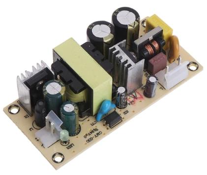
A 12 V 3A power supply unit was used as a power supply. The price of 4 USD and just a magical quality. I ordered it here.
I need to note that the powerful 4-port USB charger AUKEY 5V, 2.4 A per each USB port, connected to the SIM800L is not enough. During the loading of the SIM800 module, the maximal power consumption and the voltage on the GSM module drop to 3 V. The module did not even startup.
Code to work with SIM800L on ESP32
The code was tested on the 38-inch MH-ET Live ESP32 Devkit 38 pins. This piece of code in the project is in the form of a *. cpp file, so simply rename the Init_GSM_SIM800L () function to setup () and add the loop () function.
#include "GSM_SIM800L. H"
/*
* There are three serial ports on the ESP known as U0UXD, U1UXD and U2UXD.
*
* U0UXD is used to communicate with the ESP32 for programming and during reset/boot.
* U1UXD is unused and can be used for your projects. Some boards Use this port for SPI Flash access though
* U2UXD is unused and can be used for your projects.
*
*/
#define TINY_GSM_MODEM_SIM800
#define DEBUG/enable DEBUG mode
#include < TinyGsmClient. h.
#define RXD2 16
#define TXD2 17
#define Max_Modem_Reboots 5
#define APN_NAME "internet.beeline.ru"
#define APN_USER "Beeline"
#define APN_PSWD "Beeline"
#define GSM_AUTOBAUD_MIN 9600
#define GSM_AUTOBAUD_MAX 38400
Set your CAD pin (optional)
#define SIM_PIN ""
Define your board pin here
#define LED_PIN 27
TinyGsm modemGSM (SERIAL2);
int Modem_Reboots_Counter = 0;
Command must be without AT prefix
/* String sendAT (String command)
{
modemGSM. sendAT (GF (command));
if (modemGSM. waitResponse (GF (GSM_NL))! = 1) {
return "Empty";
}
String res = modemGSM. Stream. readStringUntil (' n ');
modemGSM. waitResponse ();
return res;
}*/
Command must be without AT prefix
String sendAT (String command)
{
String response = "";
Serial2. println ("AT" + command);
while (! Serial2. Available ());
Response = Serial2. readString ();
return response;
}
String printAT (String command, String message = "")
{
String res = "";
if (Message! = "")
{
Serial. println (message);
}
if (Command! = "")
{
Serial. println ("AT" + command);
res = sendAT (command);
Serial. println (RES);
}
return res;
}
void RestartGSMModem ()
{
Serial. println ("Restarting GSM...");
if (! modemGSM. Restart ())
{
Serial. println ("Tfaille. :-(rn ");
ESP. restart ();
}
if (Modem_Reboots_Counter < Max_Modem_Reboots)
{
Init_GSM_SIM800L ();
}
Modem_Reboots_Counter + +;
}
String GSMSignalLevel (int level)
{
Switch (level)
{
case 0:
Return "-115 dBm or less";
case 1:
Return "-111 dBm";
Case 31:
Return "-52 dBm or greater";
Case 99:
Return "not known or not detectable";
default:
if (Level > 1 & & Level < 31)
Return "-110... -54 dBm ";
}
return "Unknown";
}
String GSMRegistrationStatus (RegStatus State)
{
Switch (state)
{
Case REG_UNREGISTERED:
Return "Not registered, MT is not currently searching a new operator to register to";
Case REG_SEARCHING:
Return "Not registered, but MT is currently searching a new operator to register to";
Case REG_DENIED:
Return "Registration denied";
Case REG_OK_HOME:
Return "Registered, home Network";
Case REG_OK_ROAMING:
Return "Registered, roaming";
Case REG_UNKNOWN:
return "Unknown";
}
return "Unknown";
}
String SwapLocation (String location)
{
int i = location. indexOf (', ');
Int j = location. indexOf (', ', i + 1);
String longitude = location. substring (i + 1, j);
i = location. indexOf (', ', J + 1);
String latitude = location. substring (j + 1, i);
Return latitude + "," + longitude;
}
void Init_GSM_SIM800L () {
Serial2. Begin (9600, SERIAL_8N1, RXD2, TXD2);
Serial. println ("Serial GSM Txd is on pin:" + String (TXD2));
Serial. println ("Serial GSM Rxd is on pin:" + String (RXD2));
pinMode (LED_PIN, OUTPUT);
Delay (3000);
TinyGsmAutoBaud (Serial2, GSM_AUTOBAUD_MIN, GSM_AUTOBAUD_MAX);
String info = modemGSM. getModemInfo ();
Serial. println (info);
if (! modemGSM. Restart ())
{
RestartGSMModem ();
}
Else
{
Serial. println ("Modem restart OK");
}
printAT ("+ CMEE = 2", "Enable + CME ERROR: < Err > result code and use verbose < err > values.");
printAT ("+ COPS =?", "Show List of available operators")
if (modemGSM. getSimStatus ()! = 3)//Printt ("AT + CPIN?", "Check PIN Code Status"). startsWith ("+ CME ERROR:"))
{
Serial. println ("Check PIN code for the SIM.");
if (SIM_PIN! = "")
{
Serial. println ("Try to unlock SIM PIN.");
modemGSM. simUnlock (SIM_PIN);
Delay (3000);
if (modemGSM. getSimStatus ()! = 3)
{
RestartGSMModem ();
}
}
}
if (! modemGSM. waitForNetwork ())
{
Serial. println ("Failed to connect to network");
RestartGSMModem ();
}
Else
{
RegStatus registration = modemGSM. getRegistrationStatus ();
Serial. println ("Registration[" + GSMRegistrationStatus(registration) + "]:");
Serial. println ("Modem network OK");
}
Serial. println (modemGSM. gprsConnect (APN_NAME, APN_USER, APN_PSWD)? "GPRS Connect OK": "GPRS Connection failed");
BOOL stateGPRS = modemGSM. isGprsConnected ();
if (! stateGPRS)
{
RestartGSMModem ();
}
String state = stateGPRS? "Connected": "Not Connected";
Serial. println ("GPRS Status:" + state);
Serial. println ("CCID:" + modemGSM. getSimCCID ());
Serial. println ("IMEI:" + modemGSM. getIMEI ());
Serial. println ("Operator:" + modemGSM. getOperator ());
IPAddress local = modemGSM. localIP ();
Serial. println ("Local IP:" + Local. toString ());
int csq = modemGSM. getSignalQuality ();
if (CSQ = = 0)
{
Serial. println ("Signal quality is 0. Restart modem. ");
RestartGSMModem ();
}
Serial. println ("Signal quality:" + GSMSignalLevel (CSQ) + [" + String(csq) + "]"");
int battLevel = modemGSM. getBattPercent ();
Serial. println ("Battery level:" + String (battLevel) + "%");
float battVoltage = modemGSM. getBattVoltage ()/1000.0 F;
Serial. println ("Battery voltage:" + String (battVoltage));
String gsmLoc = modemGSM. getGsmLocation ();
Serial. println ("GSM location:" + gsmLoc);
Serial. println ("GSM location:" + SwapLocation (gsmLoc));
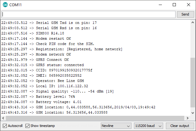
}After you have run the code, the result will be as following: