For development of IoT devices it is necessary to use various GSM modules. Unfortunately, NB IoT or LoraWAN chips at the moment cost at least three times more expensive, so in most projects their use is unjustified until the cost decreases.
The Module is well documented. The Documentation is here. Site curve. Download the documentation officially is not easy. 🙁 Therefore, we use a direct link that does not require registration, for all the necessary documentation and firmware for SIM800C. Direct link to the documentation and firmware tools for SIM800x. Schematic Documentation.
There are several variants Of SIM800C modules on Aliexpress. Link here. In This example, I’ll discuss the option of a 5V-based TTL converter on the motherboard.<-3,3V и преобразователем напряжения с 5V до ~3,7 Вольт (стандартное напряжение Li-Ion батарей сотовых телефонов). и=”” преобразователем=”” напряжения=”” с=”” 5v=”” до=”” ~3,7=”” вольт=”” (стандартное=”” напряжение=”” li-ion=”” батарей=”” сотовых=””></-3,3V и преобразователем напряжения с 5V до ~3,7 Вольт (стандартное напряжение Li-Ion батарей сотовых телефонов).>
In principle, you can use a cheaper version of the module SIM800L, adapting the TTL level under 5V Arduino using a resistor voltage divider, or ordering a fee bi-directional TTL converter 5V <->3V price in the area $0.5 and ADDING DC-DC Down-step module to reduce the voltage from 5V to 3.7 V at the price of $0.3 but in aggregate the price will be roughly the same, no savings.</->
However it is necessary to understand that at addition of bidirectional TTL converter of levels on it it is necessary to submit a reference voltage equal to a level of admissible voltage at input SIM800, and it is ~ 2.9 V, instead of 3.3 V which to take nowhere, as exit VDD_EXT from Chip SIM800 not Displayed.
The Battery can be directly connected to the Vbat stump. At This entrance it is possible to measure tension on a chip. It is 3.7 V, the built-in voltage converter works fine, although the scheme is simpler than the cheapest DC-DC step down converter.

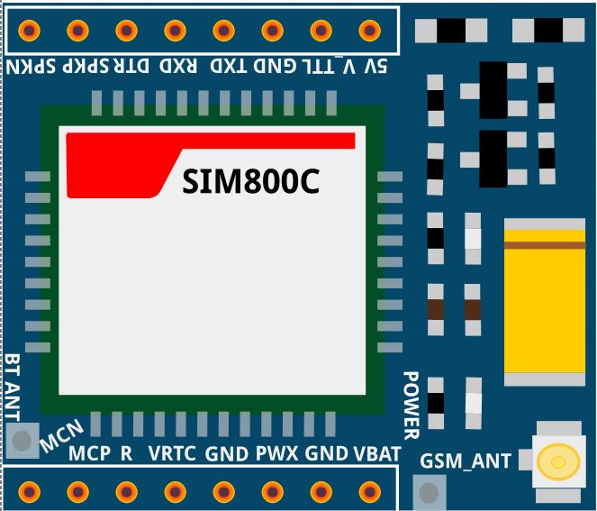
Circuit Board SIM800C
The Datasheet module Specifies the maximum level of the logical unit at the RX input-3.1 B (with a minimum of 2.1 V). To convert TTL levels on the board SIM800C is divorced converter. In The downgrade it was enough to put the converter only on RX input, because microcontrollers Arduino/ESP8266/ESP32 are sensitive to low input voltage TTL with SIM800C.
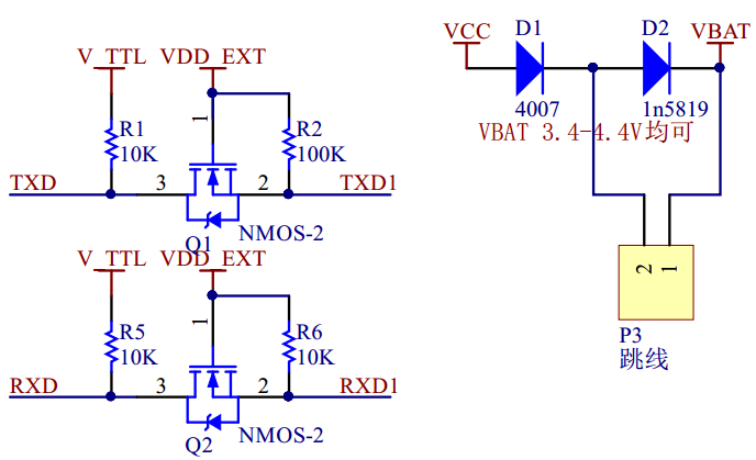
The two-directional level converter Scheme is quite standard and provides a voltage conversion of logical 1 to SIM800 to the VDD_EXT level. This tension is removed with SIM800 and by datasheet meets the 2.8 V.
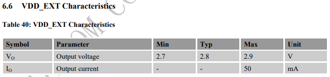
Accordingly, at the input of module SIM800 the level converter provides voltage logical 1 not above 2.9 V at maximum value.
Since the bi-directional conversion to RX is not required, in theory, one could use a cheap resistive divider, as specified in the article on connecting the module SIM800L. Detailed circuitry connects this module to ESP32 and the program code in my article.

Resistive divider when connecting inputs SIM800 directly to Arduino
Probably, in this case we used more expensive scheme for minimization of power consumption of the module and full coordination of levels for microcontrollers which do not perceive low level of the logical unit.
Note that if you use a cheap module SIM800C/L Without a level converter, even if you connect it to ESP8266/ESP32 with the logic level of 3.3 V instead of the maximum 3.1 V specified in the datasheet, you can disable SIM800. At least I have one module SIM800L stopped reacting to RX. Apparently, there are no protective diodes inside the chip, or they failed even with such a slight difference in voltage.
Therefore, if you connect the SIM800 module without the level converter to ESP8266/ESP32, you also need to add a resistive divider to the RXD input.

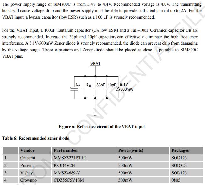
The supply Voltage of the module SIM800 (VBAT) 3.4-4.5 V, recommended 4 V with a maximum current up to 2A. The Module is sufficiently voracious, so it can not be fed from the board Arduino and low-power USB charges, do not disable them.
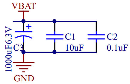
The board already has a diluted filter to suppress the impulse interference to ensure stable operation of the module, but, as experience shows, this filter is not enough when working from simple power supplies.
The SIM card Slot, unlike the inexpensive module SIM800L, is connected to a chip with the protection of a diode assembly SMF05C. It protects the SIM card chip and SIM800C from static electricity.
Disadvantages of SIM800C Board
I Can’t say that the SIM800C module is designed successfully. Comments are as follows:
- The Distance between the Combs does not multiple 2.54 mm, so the module does not rise in the breadboard layout boards. This problem is not even at the cheap fee SIM800L. She gets up in a mock-up fee without a problem. This is a very big JAMB developers!!!
- To reduce the voltage from 5V to 3, 7V uses a circuit with two diodes. As stated in the article, the voltage drop on the diodes in the normal operation of the order of 0.6-1, 2V and SIM800 enough voltage to work. However at peak values of currents the voltage drop increases and on a chip the voltage can be below 3.3 V. As a result, for example, when the power consumption is high, the module can be overloaded many times. Therefore I recommend to feed the module via the VBAT input voltage 3.8 V C DC-DC voltage converter (DC-DC stepdown Converter) or from battery.
SIM800C Module Board Pinup
- 5V: Power supply pin, the only input DC5V, used to power the board.
- V_TTL: Access control Board microcontroller core target voltage of 5V/3.3 V (according to its own microcontroller is much to distinguish kernel V), this pin is used to convert the GSM Module board and TXD for the RXD TTL logic. The Description is lengthy. On this pin it is necessary to submit 5V at connection to cards with level of logic 5V (for example, Arduino) and 3, 3V at connection of GSM module to ESP8266/ESP32.
- GND: Power supply ground
- TXD: Send pin serial port module, TTL level (not directly connected to RS232 level)
Rxd : Receive pin serial port module, TTL level (not directly connected to RS232 level)- DTR: Data Terminal Ready
- SPKP: Core Audio Output pin
- SPKN: Core Audio Output pin
- MICN: Core Audio input
- MICP: Core Audio input
- RI: Ring Core PIN Tips
- VRTC: RTC pin External battery
- GND: Power supply ground
- PWR: This pin can turns down or turns off the module. This pin must be closed on the GND for a time not less than 1 s to enable the module. For the module To start immediately when switched on-PWR are shorted on GND.
- GND: Power supply ground
- VBAT: Lithium battery input pin, 3.3 V-4.4 V
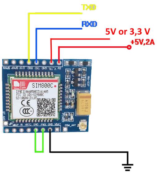
Connection Diagram SIM800C C USB-to-TTL converter
Before using the module SIM800C with microcontrollers it is necessary to check its operability connecting with the converter USB to TTL.
SIM800C connection Table with USB-to-TTL converter
| SIM800C Pin | USB-To-TTL converter | BP + 5 V | Notes |
| Txd | Rxd | ||
| Rxd | Txd | ||
| Gnd | Gnd | Gnd | |
| + 5V | + 5V | Power supply at the peak current at least 1 A!!! | |
| V_TTL | + 5V | ||
| Pwx | Gnd | Shorten the PWX pin on the GND so that the module Starts immediately when the power is turned on. |
It is Better to feed first on the GSM module, and then connect the USB to the PC, but it is not critical.
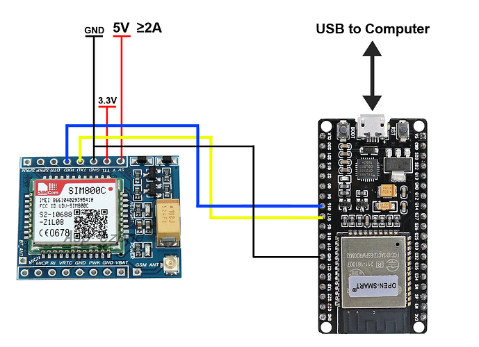
SIM800С Connection Scheme with ESP32
In the picture you need to add a connection between PWX and GND! Detailed Wiring diagram SIM800L to ESP32 with sample code in the article.
Testing SIM800
- Launch Arduino IDE.
- In the port settings (Tools-> Port), select the port on which the USB-to-TTL converter works.
- Turn to Tools-> Serial Monitor (Ctrl-Shift-M).
- Choose the speed of 115200. Somewhere slips that the chip has automatic speed detection. My tests don’t work. 🙂
- Typing AT and entering. The AT commands SIM800 Documentation is here.
- If the module is working and is connected correctly, the answer will be “OK”. If the module has defined the SIM-ku and has registered in the network of the operator, there will be expanded information.
AT
Ok

+ CPIN: READY

Call Ready

SMS Ready
- Send command: AT + COPS =? Afte
r a few seconds of waiting, you will see a response like: + COPS: (2, “Bee Line GSM”, “BeeLine”, “25099”), (1, “MTS”, “MTS”, “25001”), (1, “MOTIV”, “Motiv”, “25020”), (1, “MegaFon”, “MegaFon”, “25002”),, (0-4), (0-2). The Module “sees” the nearest honeycomb. It’S good. - Check the status of the PIN code on the SIM card with the c
ommand: AT + CPIN? If there is ERROR-something is wrong. - Run the command: AT + CMEE = 2. This command provides the most detailed information when an error message is displayed. Save the command: AT&W.
- Turning Komundu AT + CPIN? A detailed error code Appears. For Example, in my case: + CME ERROR: SIM not inserted.
- Check the installation of the SIM card. SIM slot is broken up on the module “without protection from the fool”, i.e. Allows you to insert a SIM-card in any way, without the usual restrictions on the cell phone or other types of slots. On the SIM slot finely there is a pictogram of the correct installation of the card.
- Repeat the command AT + COPS =? The Answer has changed. The lines “Call Ready” and “SMS Ready” Appeared, so the card was determined normally and registered in the network of the operator:
AT + COPS =?
Call Ready

SMS Ready

+ COPS: (1, "Bee Line GSM", "BeeLine", "25099"), (1, "MOTIV", "MOTIV", "25020"), (3, "MTS", "MTS", "25001"), (3, "MegaFon", "MegaFon", "25002"),, (0-4), (0-2)

Ok
- Send the command AT + CSQ to get the signal level. The First digit in the response must be different from zero. For example, + CSQ: 23.0.
- Check the registration of the operator’s network with the command AT + CREG? Correct Answer: + CREG: 0.1
Error + CSQ: 0.0
If the command to get the signal level AT + CSQ returns + CSQ: 0.0, there will probably be problems with the registration on the network. AT + CREG Team? will return + CREG: 0.2 instead of + CREG: 0.1. What actions to resolve the error:
- Check in another device that the SIM is correctly registered in the network.
- Insert in SIM800 in accordance with the icon on the slot and check the command AT + CPIN that the SIM card is determined correctly.
- AT + CBAND Team? Check that SIM800 is configured for all frequency ranges. On my module, when it is normally registered in the Bilaine network, the result is: DCS_MODE, ALL_BANDS.
- The Main point on which to pay attention!!! No matter what the current holds the power supply or DC-DC step-down module, though 3A and you personally convinced, try to run SIM800 from the battery. Take the battery from the mobile phone to 3.7 V or Li-Ion element 18650 on 3.7, 5 and attach plus batteries to the V_BAT stump, and minus-to the GND.
- After A short time check the signal level AT + CSQ. Most Likely the problem with registration will resolve.
All GSM modules, no matter, expensive SIM800 or cheap M590 are EXTREMELY sensitive to the quality of the power supply. And It is not only in the current, but also in Pulsa. I was drinking SIM800C from different PSU with Macacid current up to 2.1 A and it was normally included, answered at commands, but not logged in the network. After connecting to the battery TR 18650 the network was immediately found.
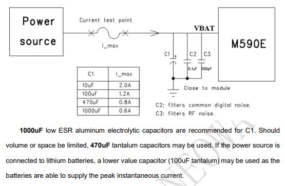
Below are the clippings from the design guide for the modules SIM800 and M590. They almost converge in the filtration block. It is Necessary to put ceramic capacitors on 10 pF and 33 pF (at M590 on 100 pF) for smoothing of high-frequency pulsations and electrolytic at least on 100 uF, and it is better on 1000 uF.
Sending SMS via SIM800
For the test work try to send SMS. To start, send the command: AT + CMGF = 1. If there is an ERROR-most likely did not pass the registration of SIM-ki in the network.
| AT command | Answer | Notes |
| AT + CMGF = 1 | Ok | We Translate into text mode of sending messages. |
AT + CSCS = “GSM” | Ok | CharSet: “GSM” GSM 7 bit default alphabet (3GPP TS 23,038); “UCS2” 16- bit universal multiple-octet coded character set (ISO/IEC10646); UCS2 character strings are converted to hexadecimal numbers from 0000 to FFFF; e.g. “004100620063” equals three 16-bit characters with decimal values 65, 98 and 99 “IR A” International reference alphabet (ITU-T T. 50) “H EX” Character strings consists only of hexadecimal “PCCP” PC Character set Code “PCDN” PC Danish/Norwegian Character Set “8859-1” ISO 8859 Latin 1 Character set |
| AT + CSCS? | + CSCS: “GSM” | Check that the correct code table has been installed correctly. |
AT + CMGS = “+ 796019xxxxx” | > | The phone Number is required with +, otherwise there will be an error message: + CMS ERROR: Invalid input val ue. After The command is run, you will be prompted to enter the text of the message to be completed by sending CTRL-Z (0x1A or (char) 26). Unfortunately, Arduino Serial Monitor does not allow you to send this code, so only programmatically. |
TCP Data Transfer
Next, I bring AT commands to establish TCP connection via GPRS.
| AT command | Answer | Notes |
| AT + CPIN? | + CPIN: READ YOK | SIM PIN Check |
| AT + CSQ | + CSQ: 23. 0 OK | Check the signal level. First digit-Signal level <rssi >: 0-115 dBm or less 1 – 111 dBm 2… 30- 110.</rssi> .. -54 dBm 31 -52 dBm or greater 99-no t known or not Setectabrlethe Second d igit-the number of errors in the channel. 0-Good. |
| AT + CREG? | + CREG: 0, 1OK | First Digit <n>: 0-Disable Network registration unsolicited result Code 1 -Enable Network registration unsolicited result code + CREG: 2 -Enable Network registration unsolicited result code with Location Informiatons econd digit <stat>: 0 -Not REGISTERED, MT is not currently searching a new operator to register to 1 -Registered, home network-correct variant 2-Not Registered, but MT is currently searching a new operator to register to 3-Regis tration denied 4-Unknow n 5-Register ed, roaming</stat> </n> |
| AT + CGATT? | + CGATT: 1OK | GPRS Service Status-a <stat>: 0-Detached 1- Attached-the correct option</stat> |
| AT + CIPSHUT | SHUT OK | Deactivate GPRS PDP Context. In the dock the developer has not specified this command, but without it I have not passed the command APN installation. |
| AT + CSTT = “internetnet. Beeline. Ru”, “Beeline”, “Beeline” | Ok | Install APN. In The example-for the operator “Beeline”. |
| AT + CSTT? | + CSTT: “Internet. Beeline. Ru”, “Beeline”, “Beeline” | Check that APN is preserved. |
| AT + CIICR | Ok | We will switch to the wireless connection mode (GPRS or CSD). |
| AT + CIFSR | 100.89.139.161 | We Get a dynamic IP address dedicated to the operator. |
| AT + CIPSTART = “TCP”, “116.228.221.51”, “8500” | Ok | Install a test TCP connection to a Chinese test server. |
Sending Data over HTTP
AT + SAPBR = 3.1, “CONTYPE”, “G
PRS” AT + SAPBR = 3.1, “APPN”, “internetnet.
Beeline. Ru” AT + SAPBR = 3.1,
“USER”, “Beeline” AT + SAPBR =
3.1, “PWD”, “Beeline” AT + SAPBR = 1.1-Set GPRS
Connection at + HTTPINIT-Initialization of h
ttp Service + HTTPPARA = “CID”, 1- Setting CID parameter for HTTP se
ssion AT + HTTPPARA = “URL”, “http://www.ya.ru”-Address web S
erveraat + HTTPACTION = 0-GET re
quest.-> + HTTPACTION: 0, 302, 0-302 error code-Found.
Fritzing part for SIM800C

Because I didn’t find the right fritzing part for SIM800C, I had to draw. File here.
Useful Links
- Hardware Design Manual SIM800 from the manufacturer’s website (Eng).
- Diagram of Module SIM800C (comments in Chinese).
- The AT commands SIM800 Documentation is here.
- https://simcom.ee/documents/SIM800x/SIM800_Series_download_Tools_Customer_v1.19.rar-Programmer SIM800 Modules on the manufacturer’s website.
- Sending via HTTP GET.
- Sending data to ThingSpeak via HTTP GET.
- Detailed Description of SIM800L (Rus).
- Connection of Module SIM800C (Eng).
- Connection of Module SIM800C (Eng).
- Connection of Module SIM800C (Rus).
- Connect to Arduino SIM800 (Eng).
- AT commands Neoway M590 (Eng).
- Hardware Design Manual Neoway M590 (Eng).
- Neoway M590 Plug-in
- Video on soldering module Neoway M590.
- Video on assembling, connecting and testing Neoway M590.
- Video on connecting Neoway M590 to PC.
- A Detailed description of Neoway M590 (Rus).
- Connecting Neoway M590 to the Internet
- https://www.instructables.com/id/GSMGPRS-Module-DIY-Kit/
- Neoway M590 Mini Plug-in
- Neoway M590 Mini plug-in Video
- Neoway M590 Mini is Split and connected.