In the previous article, I considered an example of a scheme to remove data from a water meter. The program method using the Bouncer2 library was used for getting rid of the contact’S slumber.
Software removal of the contact’s slumber
Getting Rid of your contacts is well described in the article “DREBEZG: Software and Hardware elimination”. In The simplest version, once the controller detects the closure of the water meter connected to the inlet, it is necessary to wait about 20 ms until the transient processes are complete and then to re-read the status. If The entrance after this time is still in the same condition, then the Reed worked.
The Code in the article is badly using delay. It is better to forget About using this function in programs for ESP8266/ESP32/Arduino, because it blocks the processing of events by other blocks of the program that are not related to the Debouncer code. You need to use Millis () or a library like Bouncer2.
Here’s a simple example of using Millis (). In it I did not connect to the output of the microcontroller led to indicate the status of the reed. Only made a conclusion of information about the status of LED in Serial.
int pinButton = 14; D5-Pin Buttons
BOOL flag = HIGH; Indicator of the flowing state, for example, LED
bool lastButton = LOW;
unsigned long currentMillis = 0;
unsigned long previousMillis = 0;
int debounceInterval = 20; 20 ms

void Setup ()
{
  pinMode (pinButton, INPUT_PULLUP);
  Serial. Begin (9600, SERIAL_8N1);
}

void Loop () {
  BOOL currentButton = digitalRead (pinButton);
  currentMillis = Millis ();

  if (currentButton! = lastButton)
  {
    previousMillis = currentMillis; Save the time of receiving the first impulse when the reed is triggered
    lastButton = currentButton;
  }
  Else
  {
    if (currentMillis-previousMillis > debounceInterval)//If The state of the button has not changed for debounceInterval
    {
      if (flag! = currentButton)//Compare the state and if it differs from the state of the button, change the state of the LED
      {
        String state = currentButton? "OFF": "ON";
        Serial. println ("Button is" + state);
        flag = currentButton;
        lastButton = currentButton;
      }
    }
  }
}
Note that in this case, the code to fix the contact’s slumber is so simple because the processes are very slow. Gercon is in a closed state a lot more transients. If the time were comparable, it would be necessary to use more complex algorithms of detecting the contact Drebesha, not to confuse with the real change of the state of the reed.
Hardware Troubleshooting
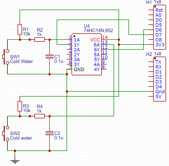
Different approaches are used For the upstep elimination of the contact’s Drebesha. The simplest option is to use the RC chain to smooth high-frequency short bursts during transient processes. Let’s consider the diagrams from the article.
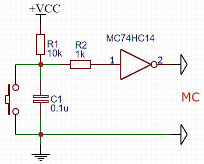
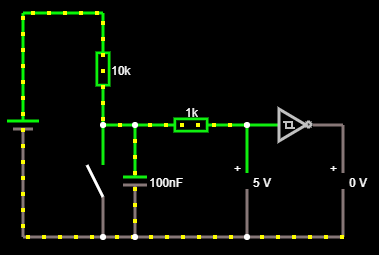
You can play with the work of the scheme here. When the button is open, the capacity C1 is charged through the R1 resistance. At the input of the inverting trigger Schmitt + VCC. Output, respectively 0.
Here The RC chain works mainly when the button is blurred. In Case of closure, the capacity is actually shorted, immediately discharging to zero. In this case, through the buttons/reed contacts under the law of Ohm I = U/R, with the resistance equal to 0, will be leaking running current. Wrong in such a way to discharge capacity. It is correct to discharge it through resistance to reduce the current discharge. Therefore, the scheme from the article is correct.
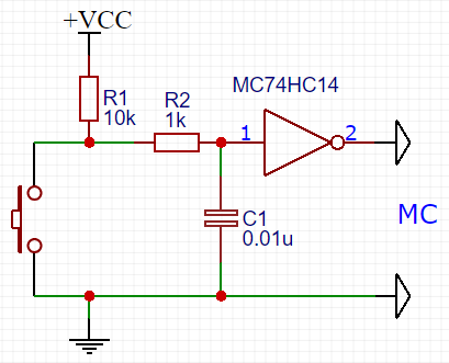
Suppression of the contact’s Drebesha for the water meter (Arduino/ESP8266/EPS32)
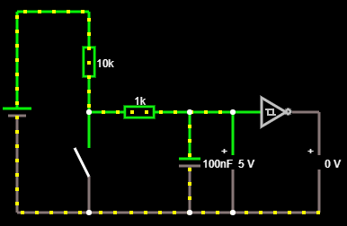
The Scheme is almost the same, but at the closure of the button capacity С2 discharged to the ground through the resistance of R4, so the current flowing through the contacts is already safe small for contacts: I = U/R = 5/1000 = 5 Ma.

T-discharge time from VDC level to Vc. Vc-the voltage at which the controller identifies the voltage level as a logical zero. I took Vc = 0.5 V. The article describes in detail the levels for ESP8266. I took a slightly lower voltage instead of 0.8 V for the voltage below which ESP8266 considers the level to be a logical zero.
t =-R2 * C1 * Ln (V0/VDC) = 1000 * 10 ^-5 * Ln (0.5/3.3) = 18.8 ms
If the capacity to increase from 0.01 Μf to 0.1 Μf, the time of discharge capacitor C1 to the level of V0 will be already 180 MS, which is quite a lot. However, in this case the processes are so slow that it is possible to leave such capacity. Its increase, and, accordingly, inertia, better smooths short bursts, reducing the probability of false positives.
Resistor R2 is also required to protect the microcontroller’s input in case it will set the logical 1 level at the input when the button is closed to the ground. Without this resistor through the input of the microcontroller began to leak a significant current, which would disable the input.
ESP8266 and Contact DREBESG
To build a Schmitt trigger on the water meter, you will need the following components (links to Aliexpress):
- Wemos D1 Mini.
- Wemos D1 Mini RTC shield. The Voltage is powered by the chip 5V, so the shield is not suitable for battery power 3.7 V.
- Wemos Breadboard.
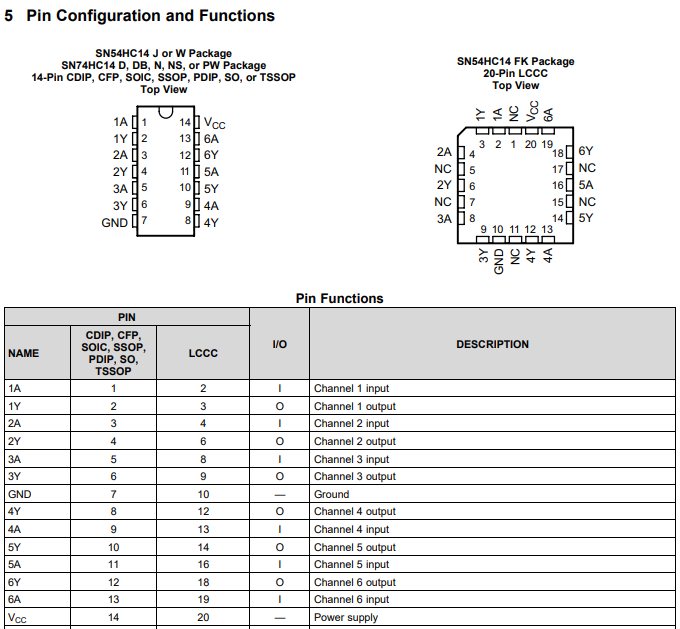
- Trigger Schmitt SN74HC14N. Datasheet.
- Resistors 1 Kom-2 pcs.
- Resistors 10 Kom-2 pcs.
- Capacitors Ceramic 100 nF (0.1 mkF)-2 pcs.
- Battery 18650
- Battery Case 18650.
Wemos D1 Mini RT uses the following contacts for RTC:
| Wemos D1 Mini (ESP8266) | Description | ESP32 |
| D1 (GPIO5) | Scl | GPIO 22 (SCL) |
| D2 (GPIO4) | Sda | GPIO 21 (SDA) |
| 5v | 5v | |
| Gnd | Gnd |
SD card reader uses contacts:
| Wemos D1 Mini (ESP8266) | Description | ESP32 VSPI | ESP32 HSPI |
| D5 (GPIO 14) | CLK/SCK | GPIO18 | GPIO14 |
| D6 (GPIO 12) | DO/MISO | GPIO19 | GPIO12 |
| D7 (GPIO13) | DI/MOSI | GPIO23 | GPIO13 |
| D8 (GPIO 15) | CS/SS | GPIO5 | GPIO15 |
There are a few Free ones: D0 (GPIO16), D3 (GPIO0), D4 (GPIO3). And these are all problematic inputs:
- The Input D0 Wemos D1 Mini does not support interrupt processing, accordingly, does not fit.
- D3, D4-inputs on which at restart/loading ESP8266 should be a certain level of a signal. If It is different, the firmware ESP8266 will not boot. That is, each reboot should disable the conclusions.
- The D4 on the Wemos D1 Mini is connected To the LED.
In general, it turns out that simultaneously connect RTC with the card reader and the module with the trigger Schmitt will not work. Or you have to add a chip in the scheme, allowing to expand the number of inputs. However, there is no special meaning in RTC and card-reader, if you use sample code to get time with NTP servers.
Why Hardware troubleshooting?
When you use the software to fix the log, the microcontroller is constantly in operation, because it has to constantly poll the states of inputs. This is a full-fledged mode of operation in which the microcontroller consumes electricity.
Everything would be nothing when the power scheme comes from the mains. But, it is not always convenient to bring the water meter 3.3/5 V from the power supply. Often used battery like 18650, and its capacity is not limitless. Regularly Recharge the battery-fun is not pleasant. Therefore, reducing power consumption is a very important point in developing such IoT devices.
In ESP8266 There are several variants of “hibernation” at which the microcontroller consumes considerably less power, living longer on a battery.
There are several approaches to reduce the power consumption of the microcontroller ESP8266/ESP32:
- Instead of programmatically polling the state of the inputs in the loop loop, use a more beautiful variant with interrupts. This method will work correctly When you use the NAP removal scheme. An Example of code using interrupts is described in the article.
- Drive ESP8266/ESP32 in deep-sleep, indicating the time through which it should wake Up to handle the state of inputs. In this case, you do not need to use hardware troubleshooting. When exiting hibernation ESP8266 could already miss the firing of the reed, so we need to interrogate the current state of inputs, and then go back to hibernation. The hibernation Time should be less than the minimum duration of the reed trigger. It is Necessary to make sure that after activation of the reed, if immediately turn off the water, it will remain in a closed state. If It is disconnected, then it is necessary to choose a time deep sleep taking into account such “force majeure”.
- To drive ESP8266/ESP32 in deep-sleep and deduce it from this state having removed the data from Gerkonov through the scheme of elimination of a drebesha of contacts and Having given an impulse on input of EXT_RSTB. To do this, you can use the free elements of the Schmitt trigger. Schematic Technician for this option will describe in another article.
- Given that ESP8266/ESP32 start instantly, you can generally tie the power circuit to the reed. I.e. Turn on the circuit when one of the coats of arms is closing.
Water meter Diagram on ESP8266 (Wemos D1 Mini)
Diagram and example of printed circuit board in the EasyEDA project. Left the I2C inputs unoccupied to connect the indicator.
The Scheme is made on Wemos breadboard.

Example of printed circuit board formed Avtotrassirovkoj in EasyEDA.
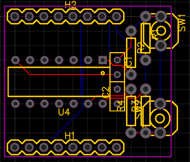
Circuit Board Shield Water meter on Wemos D1 Mini (ESP8266) with hardware removal of the pins on the Schmitt trigger
Water meter Program for ESP8266
int LED_PIN = 2; D4
int COLD_WATER_PULSE_PIN = 12; D6
int HOT_WATER_PULSE_PIN = 13; D7 4; D2
int cold_water_counter = 0;
int hot_water_counter = 0;

void Setup ()
{
  Serial. Begin (9600);
  pinMode (COLD_WATER_PULSE_PIN, INPUT); Pullup Internal Resister
  pinMode (HOT_WATER_PULSE_PIN, INPUT); Pullup Internal Resister
  pinMode (LED_PIN, OUTPUT);
  attachInterrupt (digitalPinToInterrupt (COLD_WATER_PULSE_PIN), triggerColdWater, RISING);
  attachInterrupt (digitalPinToInterrupt (HOT_WATER_PULSE_PIN), triggerHotWater, RISING);
}

void Loop () {
  int state = digitalRead (HOT_WATER_PULSE_PIN);
  Serial. println ("State:" + (String) (state));
  Delay (1000);
  digitalWrite (LED_PIN,! state);
}

void triggerColdWater ()
{
  Cold_water_counter + +;
  Serial. println ("Cold Water Consumption:" + (String) (Cold_water_counter * 10) + "L.");
}

void triggerHotWater ()
{
  Hot_water_counter + +;
  Serial. println ("Hot Water Consumption:" + (String) (Hot_water_counter * 10) + "L.");
}
Useful Links
- EMBED WITH ELLIOT: DEBOUNCE YOUR NOISY BUTTONS, PART II
- Arduino: Hardware and software troubleshooting
- Connect the button to the Arduino
- ESP8266EX GPIO High and Low Input Thresholds
- Datasheet Trigger Schmitt.
- ESP8266 Low Power Solution (ENG). Documentation from the developer.
- Output ESP8266 from hibernation (ENG).
- https://stackoverflow.com/questions/39481196/how-to-wake-esp8266-from-deep-sleep-without-continuous-resets