In the last article, I mentioned how to work with RS485 module
XY-485 with ESP8266. In this article, I’ll review how to work with
XY-485 module with microcontroller ESP32. In the next article, I’ll review using very cheap MAX485 based board, not equipped with any protection against lighting and etc., with ESP32.
Hardware for testing:
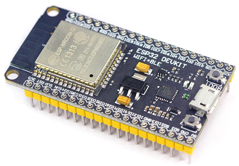
- ESP32 – 30 pin board ESP32 DevKit v1.
- RS485 – board XY-485.
- RS485 – board XY-017.
Of course better to buy 38-pin board ESP32, instead of 30 pin. The price difference is about 1,5 USD, but more GPIO pins. The boardsize is practically the same.
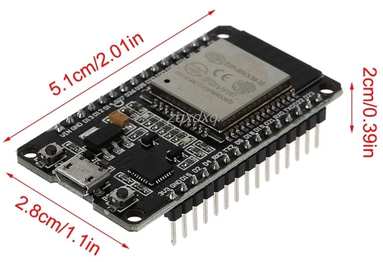
30 pin board ESP32
Serial port ESP32
On the ESP32 available three UART ports which
- U0UXD is used by USB interface converter chip (see pinout ESP32 DevKit V1).
- U1UXD possible to use for our own projects. Some boards used this pin for SPI Flash. In this case, when you request the serial port a program will crash. It’s possible to move UART1 to others GPIO, to avoid a program
cras . - U2UXD possible to use for our own projects.
On the most ESP8266 boards, U0UXD as in case of the test ESP32
To solve the problem with lack of serial
- We can use Use additional converter board I2C to one UART with
additional 8 GPIO on the chip SC16IS750. Or more powerful converter I2C to two UART based on the chip SC16IS752. - We can use software emulation with help of library ESPSoftwareSerial. Serial port software emulation work with RS485 quite stable, but better to use hardware serial port.
In the case of using ESP32, we have two additional serial UART ports. In case of converter board, it costs about 4 USD, practically as half of the ESP32 board. As a default RX/TX connected to the next GPIO pins:
| Device function | GPIO |
|---|---|
| UART 0 TX | 1 |
| UART 0 RX | 3 |
| UART 1 TX | 10 |
| UART 1 RX | 9 |
| UART 2 TX | 17 |
| UART 2 RX | 16 |
If we look at the pinout on the 30-pin ESP32 DevKit V1, then it can be noted that the UART1 port is not available and exists on the 38-pin motherboard.
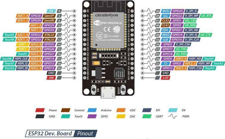
However, in ESP32, you can migrate the UART1 serial port to other GPIOs when the port is initialized.
Connection ESP32 to RS485 module
In ESP32, we use hardware UARTs. In the previous article, I mentioned that
RX / TX pins are mixed up on the XY-485 and XY-017 boards!!!
| ESP32 | XY-485 |
| Rx (PIN RX2, GPIO16) | RXD |
| Tx (PIN TX2, GPIO17) | TXD |
| VCC (Блок питания +3,3V) | |
| GND | GND |
| XY-017 | |
| Rx (PIN RX1, GPIO15) | RXD |
| Tx (PIN TX1, GPIO4) | TXD |
| VCC (Блок питания +3,3V) | |
| GND | GND |
Power supply for RS485 modules MUST BE 3,3 V,
otherwise, you can burn out GPIOs of ESP32!!!
Or use
The connection of
| Thermal sensor 1 | XY-485 |
| A+ | A+ |
| B- | B- |
| GND | GND |
| GND (Power supply -) | |
| VCC (Power supply +5V) | |
| Thermal sensor 2 | XY-017 |
| A+ | A+ |
| B- | B- |
| GND | GND |
| GND (Power supply -) | |
| VCC (Power supply +5V) |
The program to work with RS485 interface on ESP32 board
Generally speaking, there is no any significant sense to connect two RS485 interface board to ESP32. The RS485 line length is about 1200 meters with 32 pcs of RS485 connected devices. Usually, this number of devices it’s more than enough.
In this case, the example just show the possibility of using two UART on the ESP32 board. E.g., in case of using GSM or/and GPS modules with RS485 interface board two UART is the good option.
/*
 * There are three serial ports on the ESP known as U0UXD, U1UXD and U2UXD.
 *
 * U0UXD is used to communicate with the ESP32 for programming and during reset/boot.
 * U1UXD is unused and can be used for your projects. Some boards use this port for SPI Flash access though
 * U2UXD is unused and can be used for your projects.
 *
 * Tested on the 30 pin ESP32 DevKit V1 board
 *
 */

#include "ModbusMaster.h" //https://github.com/4-20ma/ModbusMaster
#include <HardwareSerial.h>

#define Slave_ID1 2
#define Slave_ID2 1

// instantiate ModbusMaster object
ModbusMaster modbus1;
ModbusMaster modbus2;

//HardwareSerial Serial1(1);
//HardwareSerial Serial2(2); //- there is no any sense to define since it already defined in HardwareSerial.h

#define RXD1 15 //RX1 pin
#define TXD1 4 //TX1 pin

#define RXD2 16 //RXX2 pin
#define TXD2 17 //TX2 pin

void setup()
{
  // Modbus communication runs at 9600 baud
  Serial.begin(9600, SERIAL_8N1);
  Serial1.begin(9600, SERIAL_8N1, RXD1, TXD1);
  Serial2.begin(9600, SERIAL_8N1, RXD2, TXD2);

  // Modbus slave ID 1
  modbus1.begin(Slave_ID1, Serial1);
  modbus2.begin(Slave_ID2, Serial2);
  modbus1.idle(yield);
  modbus2.idle(yield);
}

long lastMillis = 0;
void loop()
{
  long currentMillis = millis();
  if (currentMillis - lastMillis > 5000)
  {
    // Read 2 registers starting at 0x01
    uint8_t result1 = modbus1.readInputRegisters(0x01, 2);
    if (getResultMsg( & modbus1, result1))
    {
      Serial.println();

      double res_dbl = modbus1.getResponseBuffer(0) / 10;
      String res = "Temperature1: " + String(res_dbl) + " C\r\n";
      res_dbl = modbus1.getResponseBuffer(1) / 10;
      res += "Humidity1: " + String(res_dbl) + " %";
      Serial.println(res);
    }

    uint8_t result2 = modbus2.readInputRegisters(0x01, 2);
    if (getResultMsg( & modbus2, result2))
    {
      Serial.println();

      double res_dbl = modbus1.getResponseBuffer(0) / 10;
      String res = "Temperature2: " + String(res_dbl) + " C\r\n";
      res_dbl = modbus1.getResponseBuffer(1) / 10;
      res += "Humidity2: " + String(res_dbl) + " %";
      Serial.println(res);
    }
    lastMillis = currentMillis;
  }
}

bool getResultMsg(ModbusMaster *node, uint8_t result)
{
  String tmpstr2 = "\r\n";

  switch (result)
  {
  case node->ku8MBSuccess:
    return true;
    break;
  case node->ku8MBIllegalFunction:
    tmpstr2 += "Illegal Function";
    break;
  case node->ku8MBIllegalDataAddress:
    tmpstr2 += "Illegal Data Address";
    break;
  case node->ku8MBIllegalDataValue:
    tmpstr2 += "Illegal Data Value";
    break;
  case node->ku8MBSlaveDeviceFailure:
    tmpstr2 += "Slave Device Failure";
    break;
  case node->ku8MBInvalidSlaveID:
    tmpstr2 += "Invalid Slave ID";
    break;
  case node->ku8MBInvalidFunction:
    tmpstr2 += "Invalid Function";
    break;
  case node->ku8MBResponseTimedOut:
    tmpstr2 += "Response Timed Out";
    break;
  case node->ku8MBInvalidCRC:
    tmpstr2 += "Invalid CRC";
    break;
  default:
    tmpstr2 += "Unknown error: " + String(result);
    break;
  }
  Serial.println(tmpstr2);
  return false;
}
In the next article I’ll review very chip RS485 interface board based on the MAX3485.