When the ESP8266/ESP32/Arduino lacks GPIO you can use the MCP23017 chip to increase the number of ports by 16. Chip Control is performed on two wires I2C, communication is convenient. The Price for the chip is about $0.8. On Aliexpress is quite a large selection of options chip and two main options boards.
Wemos D1 Mini (ESP8266) is widely represented on Aliexpress at a price of less than 3 USD.
Since the board supports I2C addressing allowing to connect 8 boards, total to the microcontroller it is possible to add 128 GPIO.
Connection Scheme
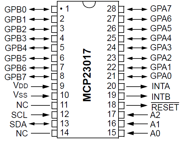
The MCP23017 Pinup is as follows:

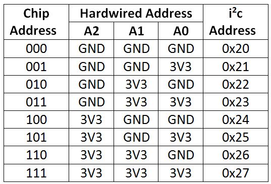
Addressing The I2C board is determined by the closure of the legs A0-2 to + 3.3 V or GND. The Addressing Table is:

Wemos D1 connection Diagram with MCP23017:
| Wemos D1 Pin Name | MCP23017 Physical Pin | MCP23017 Pin Name | Description |
|---|---|---|---|
| D1 (SCL) | 12 | Scl | I/O Serial Clock input |
| D2 (SDA) | 13 | Sda | I/O Serial Data |
| 3V3 | 18 | Reset | |
| 3V3 | 9 | Vdd | Power |
| Gnd | 10 | Vss | Ground |
| Gnd | 15 | A0 | Hardware Address Pin |
| Gnd | 16 | A1 | Hardware Address Pin |
| Gnd | 17 | A2 | Hardware Address Pin |
As a sensor, I used a line crossing sensor. The diagram is used as an example of a rain sensor board. The sensor Circuitry is the same, and for fritzing I could not find the libraries for the line crossing sensor.
When the sensor is triggered, the signal arrives at the input GPA0 and ESP8266 lights the LED switched to the output GPB0.


Program
If MCP23017 is connected to ESP8266 correctly, the device will be found when the https://playground.arduino.cc/Main/I2cScanner sketch is run.
11:04:46.058-> Scanning...
11:04:46.058-> I2C device found at address 0x20!
11:04:46.140-> done
When working with MCP23017 through the Adafruit MCP23017 library. will need a table of translation of Adafruit inputs into the names of inputs and the number of legs on the chip.
| Adafruit PIN | Pin Name | Physical Pin |
| 0 | GPA0 | 21 |
| 1 | GPA1 | 22 |
| 2 | GPA2 | 23 |
| 3 | GPA3 | 24 |
| 4 | GPA4 | 25 |
| 5 | GPA5 | 26 |
| 6 | GPA6 | 27 |
| 7 | GPA7 | 28 |
| 8 | GPB0 | 1 |
| 9 | GPB1 | 2 |
| 10 | GPB2 | 3 |
| 11 | GPB3 | 4 |
| 12 | GPB4 | 5 |
| 13 | GPB5 | 6 |
| 14 | GPB6 | 7 |
| 15 | GPB7 | 8 |
The program will also need to address Adafruit, it is different from addressing I2C.
| Address I2C | Adafruit Address | A0/P IN 15 | A1/P IN 16 | A2/P IN 17 |
|---|---|---|---|---|
| 0x20 | 0 | Low | Low | Low |
| 0x21 | 1 | HIGH | Low | Low |
| 0x22 | 2 | Low | HIGH | Low |
| 0x23 | 3 | HIGH | HIGH | Low |
| 0x24 | 4 | Low | Low | HIGH |
| 0x25 | 5 | HIGH | Low | HIGH |
| 0x26 | 6 | Low | HIGH | HIGH |
| 0x27 | 7 | HIGH | HIGH | HIGH |
The Program accepts the signal from the input GPA0 and lights the LED on the output GPB0 MCP23017 and on the board Wemos D1.
#include < Wire. h.
#include "Adafruit_MCP23017. H"

#define MCP23017_GPA0 0//Digital input on MCP23017 correspond to A0
#define MCP23017_ADDR 0x20
#define LedPin 2//A0
#define MCP23017_LED 8//GPB0

Adafruit_MCP23017 MCP;

void Setup ()
{
  Serial. Begin (9600);
  MCP. Begin ();      Use default address 0x20

  MCP. pinMode (MCP23017_GPA0, INPUT); Define GPA0 as input pin
  MCP. pinMode (MCP23017_LED, OUTPUT); Define GPB0 as output pin
  MCP. pullUp (MCP23017_GPA0, HIGH);  Turn on a 100K pullup internally

  pinMode (LedPin, OUTPUT);  Use the LedPin LED as debugging
 }

void Loop ()
{
  int value_A0 = analogRead (A0); Reads the analog input from the IR distance sensor
  BOOL value_D0 = MCP. digitalRead (MCP23017_GPA0);//reads the digital input from the IR distance sensor
  MCP. digitalWrite (MCP23017_LED,! value_D0);
  digitalWrite (LedPin, value_D0);
  Serial. println (value_D0 + "Value:" + String (value_A0));
  Delay (1000);
}
Connecting the relay to the MCP23017
Illuminated LED-Thing informative, but in life when the sensor is triggered to perform some actions, often physical: something to open and close, move, etc. So connect the relay to the LED.

As for relays and selection for microcontrollers-this is a topic for a separate article, the options are many and there are nuances. For a long time not to be wise, connected to the MCP23017 “native” relay sharpened under the Wemos D1 Mini. Such relays are inexpensive, widely presented by sellers on Aliexpress, supports TTL level 3V, i.e. Do not need to put a converter levels 3V <->5V.</->
Actually, it is easy to connect it. The Control goes on high level, i.e. On the 1-St at the control inlet D1. If It was a low level trigger, in the software it was necessary to put inversion on logic that inclusion was on 0-th, and disconnection on 1-th on input of control. And, not for all relays the program inversion works.
In general, in order not to have problems when connecting the relay to the microcontroller, working on the voltage 3.3 V, with the appropriate level of TTL logic, you need to:
- Choose High level trigger/relay.
- With the support of the TTL voltage of the logic 3.3 V.
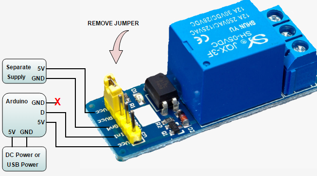
- JD VCC input to separate the 5V winding of the relay.
- Galvanic (optical) junction optronom not to “burn” the microcontroller.

So, in parallel or instead of the LED we connect MCP23017 to the relay.
| MCP23017 Pin | Wemos D1 Mini Relay Shield | Notes |
| Gnd | Gnd | |
| GPB0 | D1 | |
| 5v | On BP + 5V for relay winding control. | |
| Gnd | On BP GND for relay winding control. |
Once connected, the relay is normally switched when the sensor is triggered. You do not need to change the Program code.
CJMCU-2317 (MCP23017) Fritzing part
Did not find the Fritzing part for the board CJMCU-2317 (MCP23017), so had to create your own version. Use and do not forget to like, Nice. 🙂
Useful Links
- https://github.com/adafruit/Adafruit-MCP23017-Arduino-Library
- https://medium.com/@wilko. Vehreke/More-gpios-for-the-esp8266-with-the-mcp23017-b89f5e15cde3
- https://tronixstuff.com/2011/08/26/tutorial-maximising-your-arduinos-io-ports/
- https://arduinodiy.wordpress.com/2017/03/14/adding-an-mcp23017-16-port-io-expander-to-arduino-or-esp8266/
- http://ww1.microchip.com/downloads/en/DeviceDoc/21952a.pdf-Documentation from the manufacturer
- http://omnigatherum.ca/wp/?p=338-Fritzing part for rain sensor.