In the previous article, I reviewed how to connect very cheap RS485 module to the ESP8266. Generally speaking, it’s MAX485 chip without any protection against troubles like lightning and cost about 0,3 $ It’s better to purchase wholesale by 5 pcs. Such a way is more effective and it gives some insurance for some cases since the module can be easily burned out in
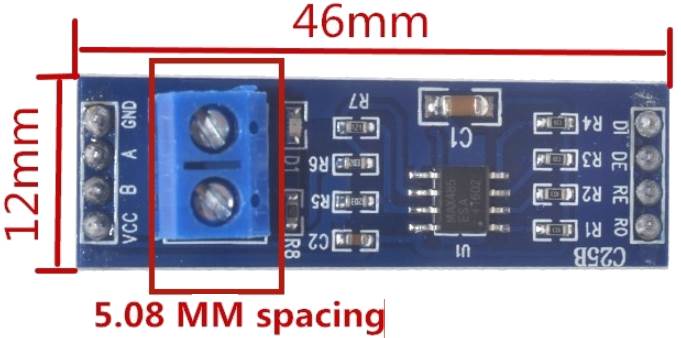
Of course in production better to use more protected, but expensive modules like previously reviewed XY-485 or XY-017. They are more protected against some industrial troubles and have automatic flow control.
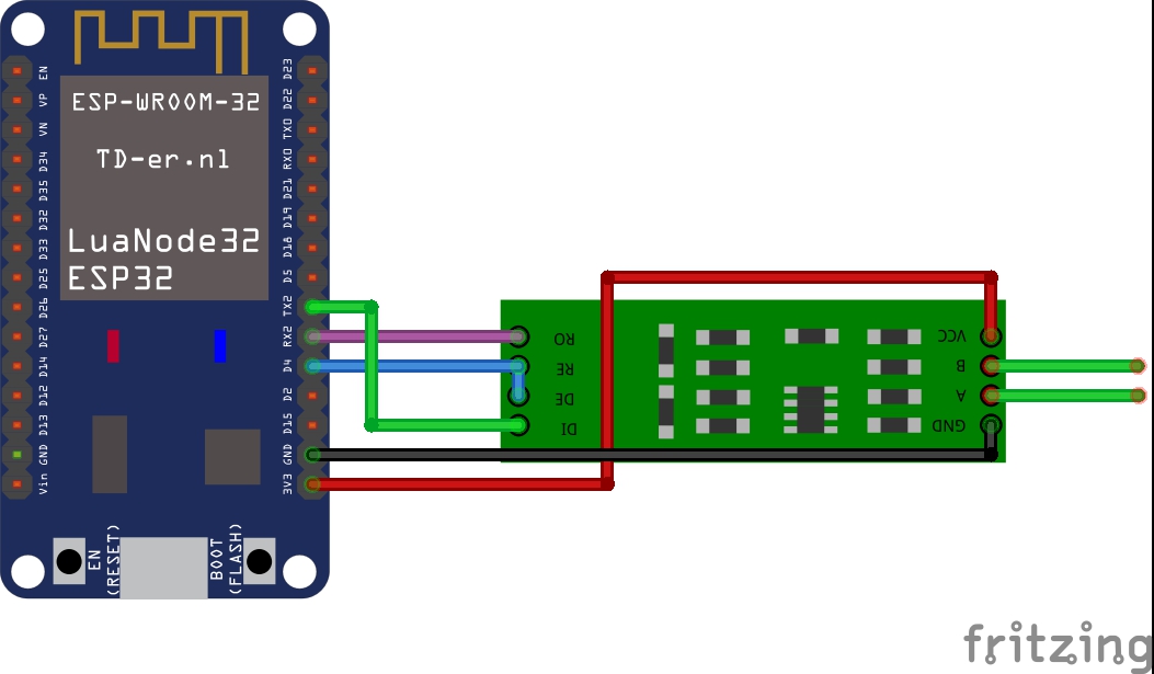
Schematic of connection RS485 with ESP32 DevKit V1
On the board ESP32 DevKit V1 exists three UART ports named as U0UXD, U1UXD и U2UXD:
- U0UXD used by USB converter of the ESP32 DevKit V1.
- U1UXD can be used for own projects. Some boards
are used this port on the pin occupied by SPI Flash. If you don’t move U1UXD to other pins it may cause an error. - U2UXD can be used for own projects.
So, on the most developers boards based on ESP32 U0UXD occupied by USB converter. Only two free UART ports are available. The s
In my
Power supply for RS485 board MUST BE 3,3V,
otherwise possible to burn out GPIO ESP32!!!
Or use TTL level converter.
| ESP32 LuaNode32 | RS485 (MAX485 chipset) |
| Rx (PIN RX2, GPIO16) | RO (receiver output) |
| Tx (PIN TX2, GPIO17) | DI (driver input) |
| DE_RE (GPIO4, D4) | DE (driver enable) RE (receiver enable) |
| 3,3V | VCC (Блок питания +3,3V) |
| GND | GND |
DI (driver input) – transmitter digital input;
RO (receiver output) – receiver digital output;
DE (driver enable) – enable transmitter to work;
RE (receiver enable) – enable receiver to work ;
Pins DE and RE are shorted.
| Thermal sensor | RS485 (MAX485 chipset) |
| A+ | A+ |
| B- | B- |
| GND | GND |
| GND (Блок питания -) | |
| VCC (Блок питания +5V) |
ESP32 program to work with RS485 board with DE/RE pins
#include "ModbusMaster.h" //https://github.com/4-20ma/ModbusMaster

/*!
  We're using a MAX485-compatible RS485 Transceiver.
  Rx/Tx is hooked up to the hardware serial port at 'Serial'.
  The Data Enable (DE) and Receiver Enable (RE) pins are hooked up as follows:
*/

#define MAX485_RE_NEG  4 //D4 RS485 has a enable/disable pin to transmit or receive data. Arduino Digital Pin 2 = Rx/Tx 'Enable'; High to Transmit, Low to Receive
#define Slave_ID       1
#define RX_PIN      16 //RX2
#define TX_PIN      17  //TX2

// instantiate ModbusMaster object
ModbusMaster modbus;

void preTransmission()
{
  digitalWrite(MAX485_RE_NEG, HIGH); //Switch to transmit data
}

void postTransmission()
{
  digitalWrite(MAX485_RE_NEG, LOW); //Switch to receive data
}

void setup()
{
  pinMode(MAX485_RE_NEG, OUTPUT);

  // Init in receive mode
  digitalWrite(MAX485_RE_NEG, LOW);

  // Modbus communication runs at 9600 baud
  Serial.begin(9600, SERIAL_8N1);

  Serial2.begin(9600, SERIAL_8N1, RX_PIN, TX_PIN);
  modbus.begin(Slave_ID, Serial2);

  // Callbacks allow us to configure the RS485 transceiver correctly
  modbus.preTransmission(preTransmission);
  modbus.postTransmission(postTransmission);
}

long lastMillis = 0;
void loop()
{
  long currentMillis = millis();
  if (currentMillis - lastMillis > 1000)
  {
    uint8_t result = modbus.readInputRegisters(0x01, 2);

    if (getResultMsg(&modbus, result))
    {
      Serial.println();

      double res_dbl = modbus.getResponseBuffer(0) / 10;
      String res = "Temperature: " + String(res_dbl) + " C\r\n";
      res_dbl = modbus.getResponseBuffer(1) / 10;
      res += "Humidity: " + String(res_dbl) + " %";
      Serial.println(res);
    }
    lastMillis = currentMillis;
  }
}

bool getResultMsg(ModbusMaster *node, uint8_t result)
{
  String tmpstr2 = "\r\n";

  switch (result)
  {
  case node->ku8MBSuccess:
    return true;
    break;
  case node->ku8MBIllegalFunction:
    tmpstr2 += "Illegal Function";
    break;
  case node->ku8MBIllegalDataAddress:
    tmpstr2 += "Illegal Data Address";
    break;
  case node->ku8MBIllegalDataValue:
    tmpstr2 += "Illegal Data Value";
    break;
  case node->ku8MBSlaveDeviceFailure:
    tmpstr2 += "Slave Device Failure";
    break;
  case node->ku8MBInvalidSlaveID:
    tmpstr2 += "Invalid Slave ID";
    break;
  case node->ku8MBInvalidFunction:
    tmpstr2 += "Invalid Function";
    break;
  case node->ku8MBResponseTimedOut:
    tmpstr2 += "Response Timed Out";
    break;
  case node->ku8MBInvalidCRC:
    tmpstr2 += "Invalid CRC";
    break;
  default:
    tmpstr2 += "Unknown error: " + String(result);
    break;
  }
  Serial.println(tmpstr2);
  return false;
}
Fritzing parts for ESP32 and RS485


One Response to Inexpensive RS485 module with ESP32 (hardware serial)