На Aliexpress представлено большое количество разнообразных внешних модулей RTC и комбинированных модулей RTC + SD карта или EEPROM. Рассмотрю наиболее интересные для использования с компактными девелоперскими платами MH ET Live Minikit (ESP32) (другой вариант поиска) или Wemos D1 mini (ESP8266).
Tiny RTC с EEPROM на 32 кБит

- Tiny RTC с EEPROM на 32 кБит:
- RTC на чипе DS1307. Напряжение питания чипа 5 V.
- Память EEPROM 32 кБит (чип AT24C32).
- Выводы не совпадают с платой Wemos D1 mini, хотя по габаритам и совместима, поэтому использовать её неудобно.
- Модуль RTC использует интерфейс I2C, однако выставить на плате адрес шины нельзя.
- Размеры модуля, мм: 28×25.
- Батарея для питания: CR2032
- Цена с доставкой в Россию: 0,34 USD
- Модуль доступен у большого количества поставщиков на Aliexpress.
Основной плюс платы — низкая цена и наличие распаянного на плате EEPROM чипа. В некоторых случаях значительная емкость SD карты не нужна и переплачивать из-за этого лишние 300 руб не хочется.
К сожалению нормального варианта этого модуля, который бы «садился» на разъем девеоперских плат найти не удалось.
RTC + SD card reader module
 | 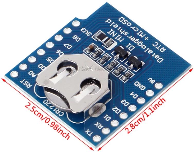 |
- RTC + SD card reader module для платы Wemos D1 mini (ESP8266) или MH ET Live Minikit (ESP32):
- RTC на чипе DS1307. Напряжение питания чипа 5 V.
- Слот Micro SD карты для логирования.
- Модуль RTC использует интерфейс I2C, однако выставить на плате адрес шины нельзя.
- Размеры модуля, мм: 28×25.
- Батарея для питания: CR1220
- Цена с доставкой в Россию: 1,55 USD
- Судя по всему разработка компании RobotDyn. Там-же есть вариант модуля без SD карты.
- В разделе документации доступны схемы.
- Модуль доступен у большого количества поставщиков на Aliexpress.
Функционально второй модуль удобнее из-за наличия слота SD карты и возможности каскадирования («сэндвич») при использовании компактных девелоперских плат MH ET Live Minikit (ESP32) или Wemos D1 mini (ESP8266). Рассмотрю работу с этим модулем подробнее.
Схема для подключения не требуется, поскольку при стекировании девелоперских плат с Wemo D1 mini datalogger нужные пины уже состыкованы. Для подключения RTC пины:
| Wemos D1 mini (ESP8266) | Описание | ESP32 |
| D1 (GPIO5) | SCL | GPIO 22 (SCL) |
| D2 (GPIO4) | SDA | GPIO 21 (SDA) |
| 5V | 5V | |
| 3.3V | 3.3V | |
| GND | GND |
Ещё раз обращаю внимание, что питание чипа RTC — 5 V. Если его запитать от 3,3 V, то он работает некорректно. Не выдает ошибки при соединении, но при запросе даты — выдает некорректную.
SD карта запитывается от пина 3.3V. При подключении к ESP32 не нужно забывать подключать это напряжение.
Data logger RTC shield (Wemos D1 mini) НЕЛЬЗЯ использоваить при питании от аккумулятора 3.7 V. 🙁
Для подключения SD карты к ESP8266/ESP32:
| Wemos D1 mini (ESP8266) | Описание | ESP32 VSPI | ESP32 HSPI |
| D5 (GPIO 14) | CLK/SCK | GPIO18 | GPIO14 |
| D6 (GPIO 12) | DO/MISO | GPIO19 | GPIO12 |
| D7 (GPIO13) | DI/MOSI | GPIO23 | GPIO13 |
| D8 (GPIO 15) | CS/SS | GPIO5 | GPIO15 |
Выводы SD карты подключаются к выводам Wemos D1 без каких-либо дополнительных схем защиты от статического электричества. Например, диодной сборкой SMF05C.
Программа
Для работы с модулем Wemos D1 mini RTC + SD card datalogger использовал следующий код из библиотеки https://github.com/Makuna/Rtc.
Библиотека Adafruit не работает.
// CONNECTIONS:
// DS1307 SDA --> SDA
// DS1307 SCL --> SCL
// DS1307 VCC --> 5v
// DS1307 GND --> GND

/* for software wire use below
#include <SoftwareWire.h>  // must be included here so that Arduino library object file references work
#include <RtcDS1307.h>
SoftwareWire myWire(SDA, SCL);
RtcDS1307<SoftwareWire> Rtc(myWire);
 for software wire use above */

/* for normal hardware wire use below */
#include <Wire.h> // must be included here so that Arduino library object file references work
#include <RtcDS1307.h>
RtcDS1307<TwoWire> Rtc(Wire);
/* for normal hardware wire use above */

void setup ()
{
    Serial.begin(9600);

    Serial.print("compiled: ");
    Serial.print(__DATE__);
    Serial.println(__TIME__);

    //--------RTC SETUP ------------
    // if you are using ESP-01 then uncomment the line below to reset the pins to
    // the available pins for SDA, SCL
    // Wire.begin(0, 2); // due to limited pins, use pin 0 and 2 for SDA, SCL

    Rtc.Begin();

    RtcDateTime compiled = RtcDateTime(__DATE__, __TIME__);
    printDateTime(compiled);
    Serial.println();

    if (!Rtc.IsDateTimeValid())
    {
        if (Rtc.LastError() != 0)
        {
            // we have a communications error
            // see https://www.arduino.cc/en/Reference/WireEndTransmission for
            // what the number means
            Serial.print("RTC communications error = ");
            Serial.println(Rtc.LastError());
        }
        else
        {
            // Common Cuases:
            //    1) first time you ran and the device wasn't running yet
            //    2) the battery on the device is low or even missing

            Serial.println("RTC lost confidence in the DateTime!");
            // following line sets the RTC to the date & time this sketch was compiled
            // it will also reset the valid flag internally unless the Rtc device is
            // having an issue

            Rtc.SetDateTime(compiled);
        }
    }

    if (!Rtc.GetIsRunning())
    {
        Serial.println("RTC was not actively running, starting now");
        Rtc.SetIsRunning(true);
    }

    RtcDateTime now = Rtc.GetDateTime();
    if (now < compiled)
    {
        Serial.println("RTC is older than compile time!  (Updating DateTime)");
        Rtc.SetDateTime(compiled);
    }
    else if (now > compiled)
    {
        Serial.println("RTC is newer than compile time. (this is expected)");
    }
    else if (now == compiled)
    {
        Serial.println("RTC is the same as compile time! (not expected but all is fine)");
    }

    // never assume the Rtc was last configured by you, so
    // just clear them to your needed state
    Rtc.SetSquareWavePin(DS1307SquareWaveOut_Low);
}

void loop ()
{
    if (!Rtc.IsDateTimeValid())
    {
        if (Rtc.LastError() != 0)
        {
            // we have a communications error
            // see https://www.arduino.cc/en/Reference/WireEndTransmission for
            // what the number means
            Serial.print("RTC communications error = ");
            Serial.println(Rtc.LastError());
        }
        else
        {
            // Common Cuases:
            //    1) the battery on the device is low or even missing and the power line was disconnected
            Serial.println("RTC lost confidence in the DateTime!");
        }
    }

    RtcDateTime now = Rtc.GetDateTime();

    printDateTime(now);
    Serial.println();

    delay(10000); // ten seconds
}

#define countof(a) (sizeof(a) / sizeof(a[0]))

void printDateTime(const RtcDateTime& dt)
{
    char datestring[20];

    snprintf_P(datestring,
            countof(datestring),
            PSTR("%02u/%02u/%04u %02u:%02u:%02u"),
            dt.Month(),
            dt.Day(),
            dt.Year(),
            dt.Hour(),
            dt.Minute(),
            dt.Second() );
    Serial.print(datestring);
}
Код не требует какой-либо настройки и начинает работать сразу.
Работа с Wemos D1 mini Datalogger через I2C (библиотека Wire.h) без использования дополнительных библиотек.
#include "Wire.h"
#define DS1307_I2C_ADDRESS 0x68

byte decToBcd(byte val)
{
  return ( (val/10*16) + (val%10) );
}

byte bcdToDec(byte val)
{
  return ( (val/16*10) + (val%16) );
}

void setDateDs1307(byte second,        // 0-59
                   byte minute,        // 0-59
                   byte hour,          // 1-23
                   byte dayOfWeek,     // 1-7
                   byte dayOfMonth,    // 1-28/29/30/31
                   byte month,         // 1-12
                   byte year)          // 0-99
{
   Wire.beginTransmission(DS1307_I2C_ADDRESS);
   Wire.write(0);
   Wire.write(decToBcd(second));
   Wire.write(decToBcd(minute));
   Wire.write(decToBcd(hour));
   Wire.write(decToBcd(dayOfWeek));
   Wire.write(decToBcd(dayOfMonth));
   Wire.write(decToBcd(month));
   Wire.write(decToBcd(year));
   Wire.endTransmission();
}

void getDateDs1307(byte *second,
          byte *minute,
          byte *hour,
          byte *dayOfWeek,
          byte *dayOfMonth,
          byte *month,
          byte *year)
{

  Wire.beginTransmission(DS1307_I2C_ADDRESS);
  Wire.write(0);
  Wire.endTransmission();

  Wire.requestFrom(DS1307_I2C_ADDRESS, 7);

  *second     = bcdToDec(Wire.read() & 0x7f);
  *minute     = bcdToDec(Wire.read());
  *hour       = bcdToDec(Wire.read() & 0x3f);
  *dayOfWeek  = bcdToDec(Wire.read());
  *dayOfMonth = bcdToDec(Wire.read());
  *month      = bcdToDec(Wire.read());
  *year       = bcdToDec(Wire.read());
}

void setup()
{
  byte second, minute, hour, dayOfWeek, dayOfMonth, month, year;
  Wire.begin();
  Serial.begin(9600);

  second = 45;
  minute = 3;
  hour = 7;
  dayOfWeek = 5;
  dayOfMonth = 17;
  month = 4;
  year = 8;
  setDateDs1307(second, minute, hour, dayOfWeek, dayOfMonth, month, year);
}

void loop()
{
  byte second, minute, hour, dayOfWeek, dayOfMonth, month, year;

  getDateDs1307(&second, &minute, &hour, &dayOfWeek, &dayOfMonth, &month, &year);
  Serial.print(hour, DEC);
  Serial.print(":");
  Serial.print(minute, DEC);
  Serial.print(":");
  Serial.print(second, DEC);
  Serial.print("  ");
  Serial.print(month, DEC);
  Serial.print("/");
  Serial.print(dayOfMonth, DEC);
  Serial.print("/");
  Serial.print(year, DEC);
  Serial.print("  Day_of_week:");
  Serial.println(dayOfWeek, DEC);

  delay(1000);
}
Micro SD карта на Wemos D1 mini datalogger
Схема для подключения модуля по-прежнему не нужна. 🙂 Все соединения работают нормельно после сборки «сэндвича» из
Wemos D1 mini (ESP8266) и Wemos D1 mini datalogger.
Проверил работу штатной библиотеки ESP8266 для работы с Micro SD картой. Тестовый пример без проблем откомпилировался и отработал. Так что модуль работает без проблем.
ВАЖНЫЙ МОМЕНТ РАБОТЫ SD карты с ESP8266!!!
Я использовал Samsung 32Gb EVO Plus отформатированную в FAT32 и с ней DataLogger не инициализировал карту. После того как отформатировал в FAT16 ESP8266 стал читать SD карту.
При этом на дешевой Micro SD «SP Elite» 16 Gb отформатированной в FAT32 проблем с чтением не возникло, ESP8266 без проблем проинициализировал карту.
В коде ниже нужно обратить внимание на CS PIN инициализации SD.init(15). На Wemos Mini D1 пин CS заведен на GPIO15, а не GPIO4.
/*
  SD card read/write

  This example shows how to read and write data to and from an SD card file
  The circuit:
   SD card attached to SPI bus as follows:
 ** MOSI - pin 11
 ** MISO - pin 12
 ** CLK - pin 13
 ** CS - pin 4

  created   Nov 2010
  by David A. Mellis
  modified 9 Apr 2012
  by Tom Igoe

  This example code is in the public domain.

*/

#include <SPI.h>
#include <SD.h>

File myFile;

void setup() {
  // Open serial communications and wait for port to open:
  Serial.begin(9600);
  while (!Serial) {
    ; // wait for serial port to connect. Needed for Leonardo only
  }


  Serial.print("Initializing SD card...");

  if (!SD.begin(4)) {
    Serial.println("initialization failed!");
    return;
  }
  Serial.println("initialization done.");

  // open the file. note that only one file can be open at a time,
  // so you have to close this one before opening another.
  myFile = SD.open("test.txt", FILE_WRITE);

  // if the file opened okay, write to it:
  if (myFile) {
    Serial.print("Writing to test.txt...");
    myFile.println("testing 1, 2, 3.");
    // close the file:
    myFile.close();
    Serial.println("done.");
  } else {
    // if the file didn't open, print an error:
    Serial.println("error opening test.txt");
  }

  // re-open the file for reading:
  myFile = SD.open("test.txt");
  if (myFile) {
    Serial.println("test.txt:");

    // read from the file until there's nothing else in it:
    while (myFile.available()) {
      Serial.write(myFile.read());
    }
    // close the file:
    myFile.close();
  } else {
    // if the file didn't open, print an error:
    Serial.println("error opening test.txt");
  }
}

void loop() {
  // nothing happens after setup
}
Подключение SD карты к ESP32 описано здесь. В цело все то-же самое. Проблем возникнуть не должно.
Полезные ссылки
- Wemos D1 mini datalogger (DS1307 + SD card) schematic and description.
- Размеры модуля Wemos D1 mini datalogger (DS1307 + SD card).
- Библиотека для работы с DS1307.
- Видеообзор модуля Wemos D1 mini datalogger (DS1307 + SD card) на русском.
- Подключение SD карты к ESP32 от разработчиков Espressif.
- Подключение SD карты к ESP32.
- ESP32 Pinout Reference: Which GPIO pins should you use?