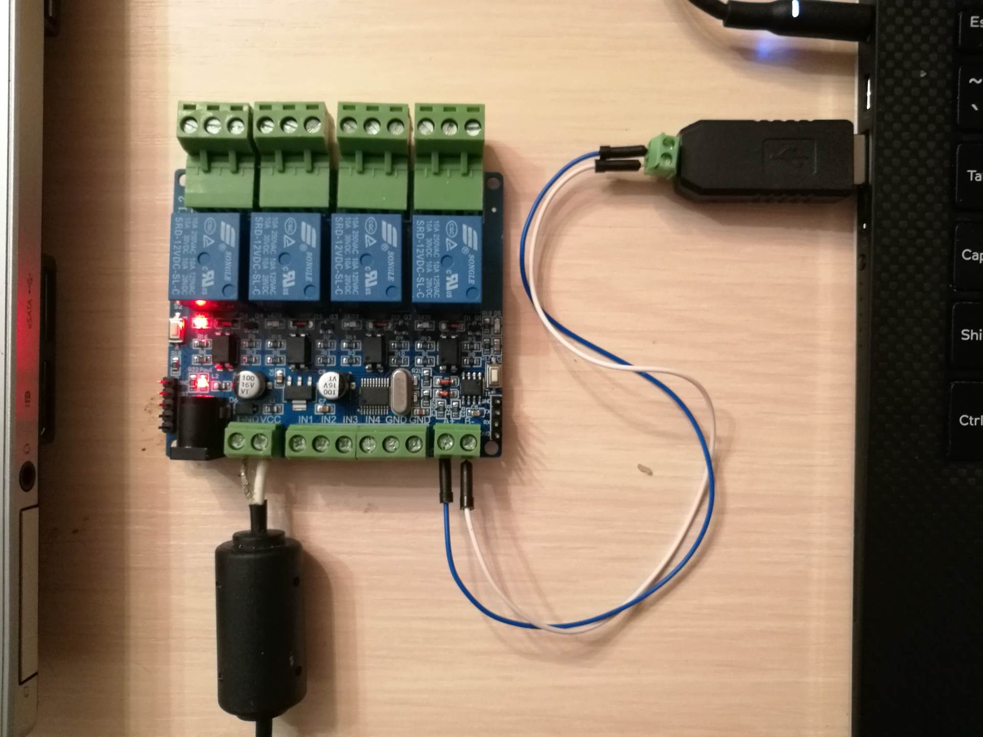
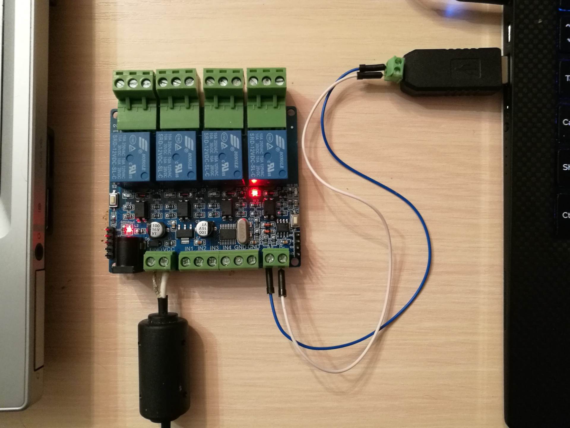
To test a device management by Modbus RTU commands, we use the circuitry of 4 relays controlled by the STM8S103 controller. (Relay MCU 4-way relay-communication board (RS-485).
I used RS485 to USB adaptor to connect to the relays board.
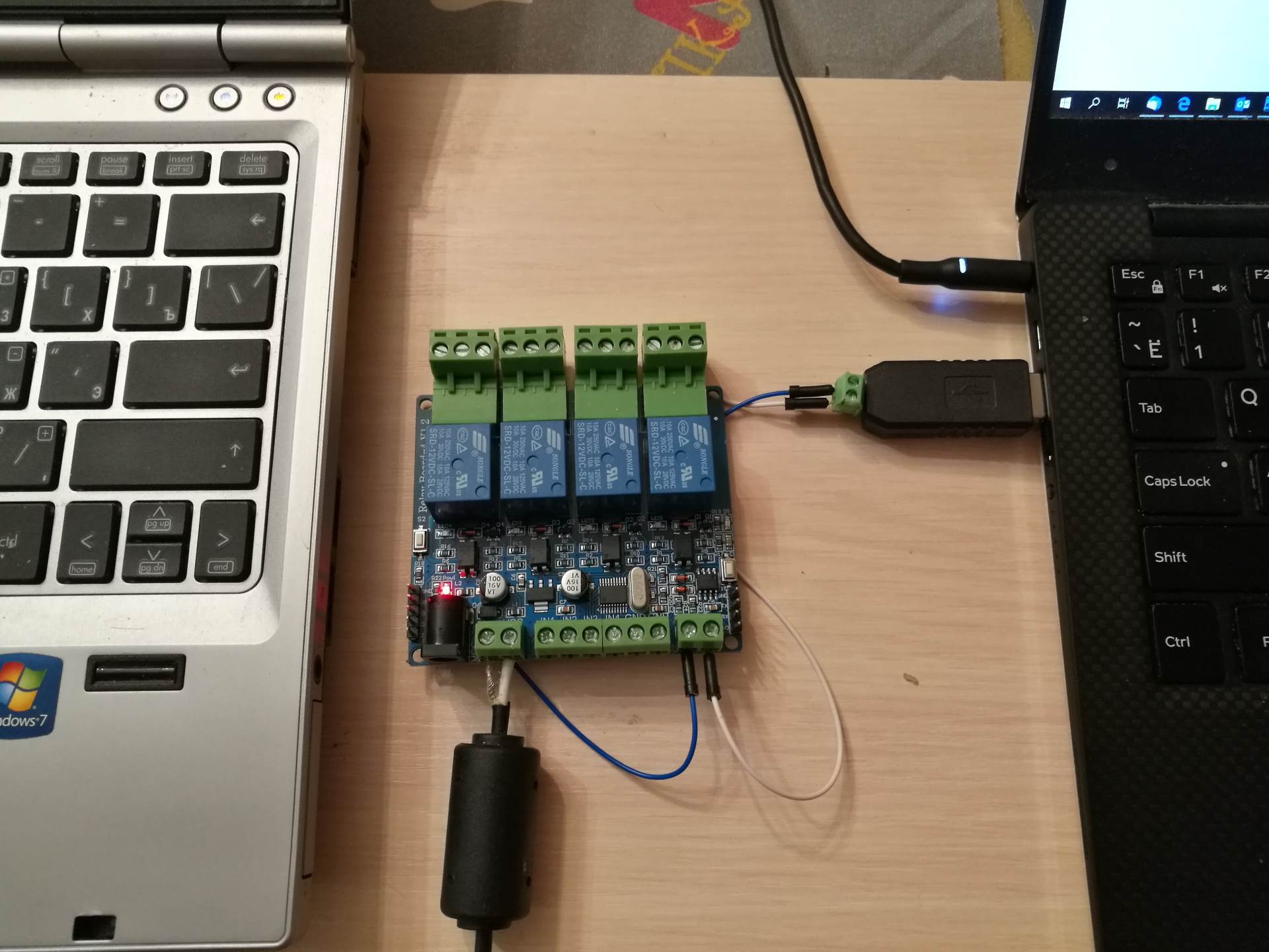
4-х relays board managed by Modbus RTU commands with USB – RS485 converter
Manage the relay
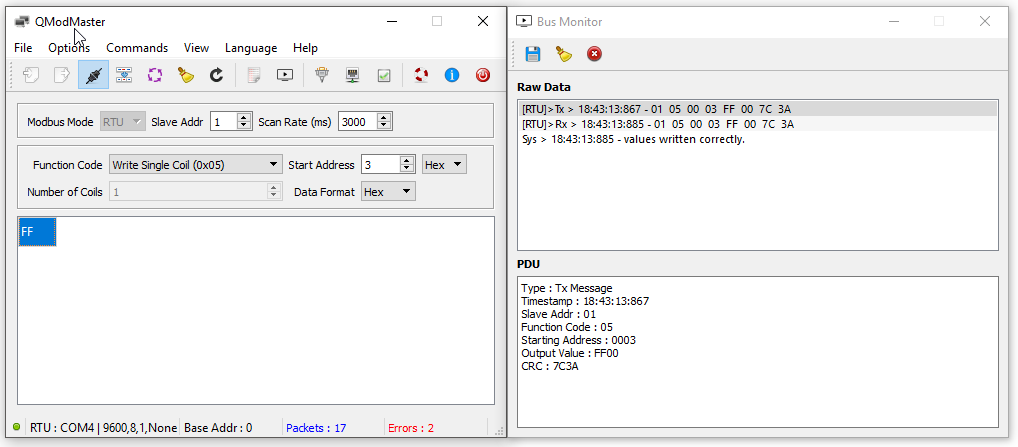
To turn a relay on/off we will use Modbus “Write Single Coil (0x05)” function.
To send the Modbus commands we will use QmodMaster application.
The example of how to use the application described in details in previous article where we learned how to work with termo/humidity sensor managed by Modbus RTU.
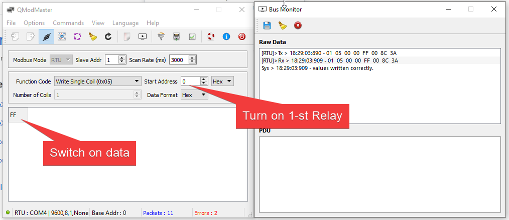
Turn on 1-st relay
After finishing the command you’ll hear the relay click and LED will light.
Turn on 1-st relay
To turn on the relay you can send any number except 0. Zero – to turn off the relay.

Turn off the 1-st relay
The screenshot with the example of turning off of the 4-st relay.
Turning off the 4-st relay
Turning off the 4-st relay
Turning on and off a relay by Modbus commands:
| Function code | Start address | Number of coils | Data | Description |
| Write Single Coil (0x05) | 0 | 1 | 1 | Turn on 1-st relay |
| 0 | 1 | 0 | Turn off 1-st relay | |
| 1 | 1 | 1 | Turn on 1-st relay | |
| 1 | 1 | 0 | Turn off 1-st relay | |
| 2 | 1 | 1 | Turn on 1-st relay | |
| 2 | 1 | 0 | Turn off 1-st relay | |
| 3 | 1 | 1 | Turn on 1-st relay | |
| 3 | 1 | 0 | Turn off 1-st relay | |
| FF | 1 | 1 | Turn on all relay | |
| FF | 1 | 0 | Turn off all relay |
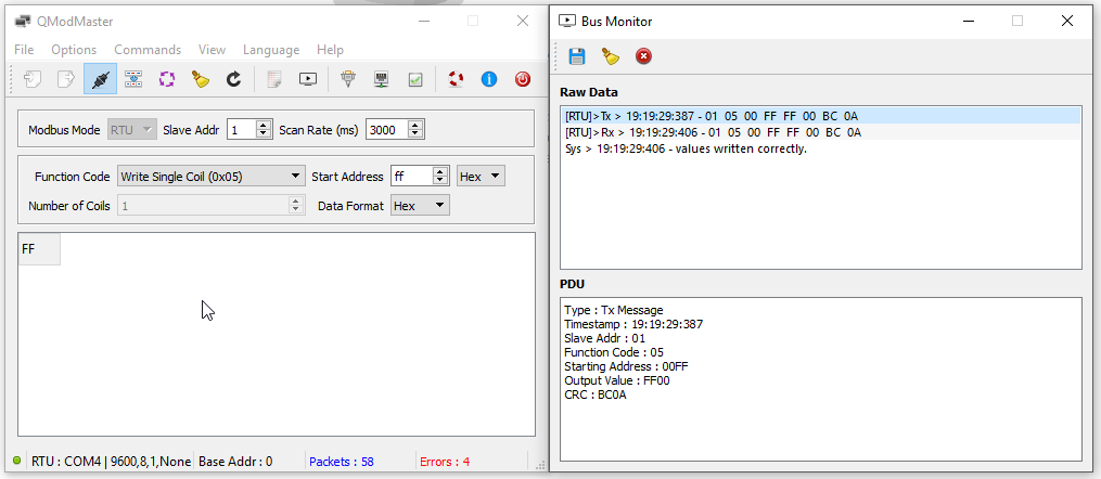
Modbus command to turn off all relays.
Read relays state
To write registers used 0х05 function – “Discrete Output Coils”. According to the table, the addressing of these registers starts from 1.
| Memory Address | Type | Memory Type |
| 1-9999 | Read-Write | Discrete Output Coils |
| 10001-19999 | Read-Only | Discrete Input Contacts |
| 30001-39999 | Read-Only | Analog Input Registers |
| 40001-49999 | Read-Write | Analog Output Holding Registers |
Accordingly, to get the state “Discrete Output Register” it is necessary to read 4 registers responsible for the state of the relay. The function is responsible for reading these registers 0х01 “Read coils”. State:
- “0” – a relay is turned off.
- “1” – a relay is turned on.
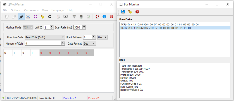
In the example turned on the 2-d and 4-th relay.
Modbus RTU <-> TCP converter
I switched the relay board from the USB <-> RS-485 converter to the Modbus RTU <-> TCP converter which was discussed in the article. Everything work ok. Relays managed over Wi-Fi.
Upd. Possibly, the detail documentation for the module by links, but, unfortunately, couldn’t download:
The seller doesn’t respond to my requests.
Useful links
- Project on Github
conc . board C0135. https://github.com/TG9541/stm8ef-modbus. A lot of useful information. - Others my articles concerning RS485 & Modbus.