In the previous article I considered the connection of the relay to the output of microcontrollers ESP8266/ESP32/Arduino through a discrete transistor, i.e. Without galvanic junction load and microcontroller.
You can simplify your life and do not be wise with the collapse of transistors, taking on Aliexpress ready module with an optical interchange on the 4-channel assembly of Optronov TLP281-4.
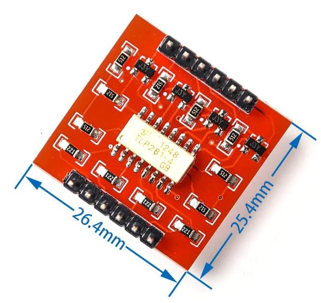
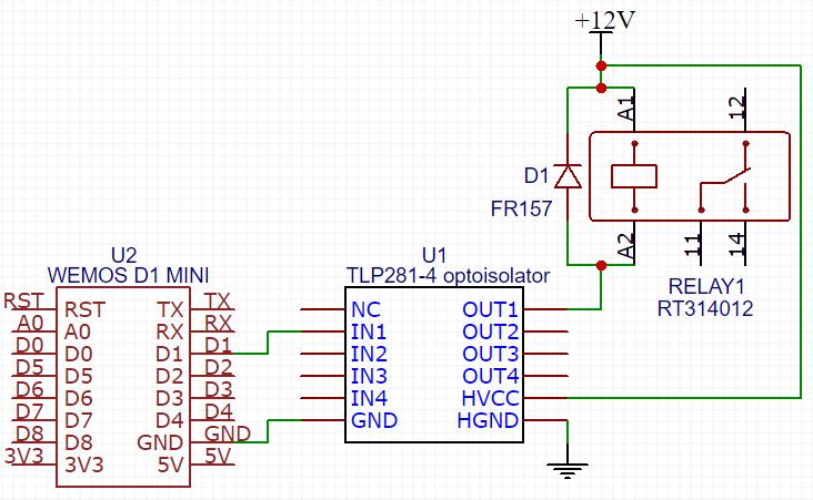
The Module is designed for galvanic junction of the microcontroller output from noisy load with high voltage. The current module is Operated with a maximum value of 50 Ma.
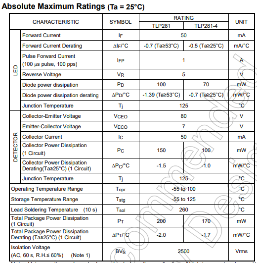
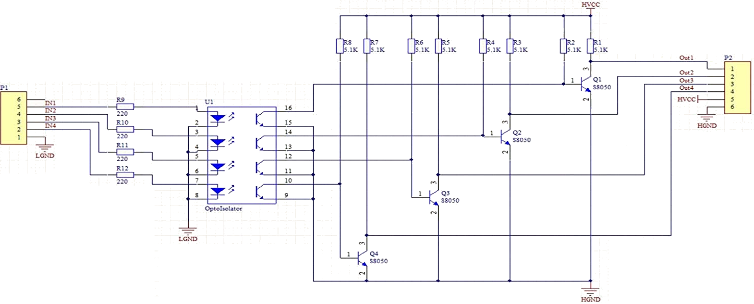
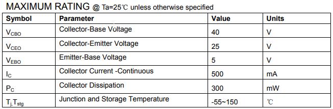
The Maximum current at the output TLP281-4 50 Ma. The Relay to this output is not directly connected, so after Optosborki installed planar transistors S8050 in the case SOT-23. They Have the maximum current of the Collector 500 Ma at the voltage Collector-emitter (VCEO) in 25V.
Accordingly, the module can commutate the load controlled by the current in 500 Ma and the maximum voltage of 24 V (according to the module documentation).
Characteristics:
- Number of Channels: 4
- Optional assembly: TLP281-4
- Transistor Output: S8050
- Input Voltage (IN1.. IN4)-3.. 5 V
- Maximum input current (IN1.. IN4): 50 Ma
- Maximum output voltage OUT1.. OUT4:24 V
- Maximum current on outputs OUT1.. OUT4:500 Ma
- Size of the board, MM: 25х24
- Availability on Aliexpress: High
Diode Parallel Relay
When connecting to Out relays it is not possible to forget about parallel shunt diode. It is written In detail here.
Diode is better to use impulse, for example, FR157. But It is possible to put and usual rectifier, for example, 1N4007.

The Program for switching on the relay through Optoizoljator on TLP281
The Code is simple. The Only point
Do not use GPIO0 (D3) and GPIO2 (D4) to control the relay!
At loading on these PINS there should be a certain condition that ESP8266 correctly loaded. If you hang the relay on these PINS, then after reset ESP8266 will load incorrectly and the program won't work.
const int LED = 2; D4
const INT relay = 4; D2 do NOT USE GPIO0 (D3) and GPIO2 (D4) to MANAGE THE RELAY

void turnOnRelay (bool state)
{
  String st = state? "ON": "OFF";
  Serial. println ("Relay State:" + st);
  digitalWrite (relay, state);
  digitalWrite (LED,! State);
}

void Setup () {
  pinMode (LED, OUTPUT);
  pinMode (relay, OUTPUT);
  turnOnRelay (LOW);
  Serial. Begin (9600);
}

void Loop () {
  Put your main code here, to run repeatedly:
  turnOnRelay (HIGH);
  Delay (5000);
  turnOnRelay (LOW);
  Delay (5000);
}