Industrial sensors reporting the change of the measured parameter by the current change in the range of 4.. 20 Ma, widely distributed. They are highly noise-resistant, so a cable of several hundred meters can be used for this sensor.
The Simplest way to connect the sensor with the current Loop 4.. 20 Ma to the microcontroller-use the following scheme:
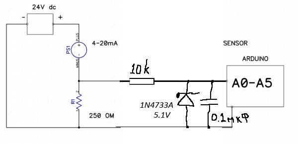
There is no galvanic junction In it. Stabilitron protects the inputs of the microcontroller from the voltage of more than 5.1 V and Replusovka. On the circuit Stabilitron and resistance R1 are calculated for the microcontroller with 5-volt level ADC (Arduino). For "clean" ESP8266/32, other elements are needed, calculated on the limit of 1 V voltage on the ADC.
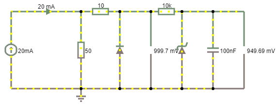
The Results of the simulation of the simplest current converter in the voltage connection to the ADC microcontroller ESP8266/ESP32
If to simulate what voltage will be on ADC of the microcontroller at a flow of the maximal current in 20 Ma, it is visible, that because of nonlinear voltampernoy characteristics of Stabilitron There is a distortion of tension and instead of 1V ADC is measured 949 mV. If you remove the Stabilitron, there is a risk of failure of the microcontroller's input in case of connection of long lines acting in the role of inductance. The Diode protects the input of the microcontroller from the negative surges of voltage.
In The first scheme, the current flowing through the resistance of 250 Ohm by the law of Ohm leads to the appearance on it of the voltage U = I
* R. Umin = 4 Ma * 250 OHM = 1 V.
Umax = 20 Ma * 250 OHM = 5 V.
Resistor corresponds to the Arduino logic level. For microcontrollers ESP8266/ESP32 unsoldered on the board with resistive divider transforming 3.3 V in in 1 ADC resistance should be R = U/I. Rmax = 3 V/20 mA = 150 Ohm. If the resistive divider voltage is not broken on the board, then the ADC voltage should not exceed 1.1 V.
Check that resistor is standard using the calculator. Or at once calculate resistance of the suitable resistor by means of Resistance calculator. Voltage Drop on the resistor with a minimum current Umin = 4 mA * 150 = 0.6 Volts.
There are more complex schemes. I Do not know which book scan, found this page on the Internet. I would be grateful if recipients forward link:
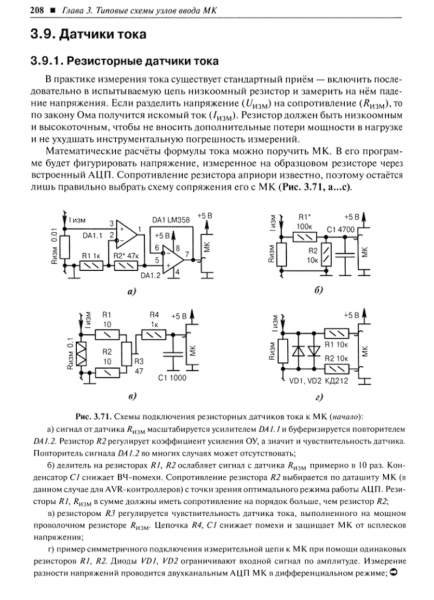
To accurately measure the current change, resistor R1 on 250 Ohm for Arduino on which the microcontroller is measuring the voltage (U = I * R) should be with a minimum tolerance: 1% or better.
Galvanic junction is not suitable Here because its characteristic is nonlinear, so it will distort measurements.
Current Conversion Fee 4.. 20 Ma in Voltage
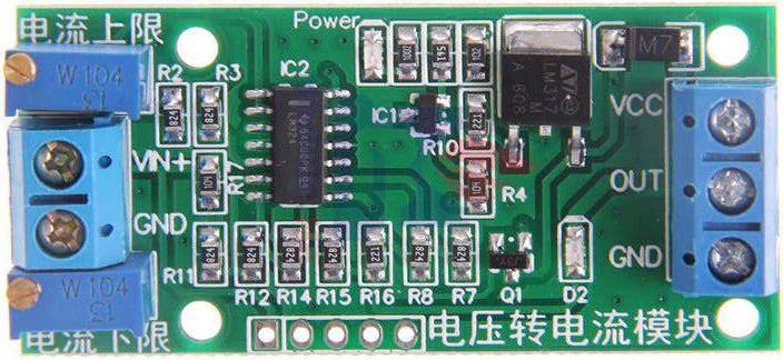
After A long search, I managed to find on Aliexpress a module that implements the conversion of current 4.. 20 Ma into tension and sufficiently protected from different misfortunes. Purchased from this seller.
Supply Voltage of Module 7-36V. If the output voltage range is 10 V, the supply voltage must be at least 12 V.

On The board is split:
- The Precision resistor on which the voltage drop is measured.
- Protection of the input from the error with polarity.
- Voltage Protection 5 V.
- An Amplifier that provides output voltage in certain ranges specified by Jamperami.
The board is Configured to the desired output voltage range by jumpers.
- ON: Jumper cap buckles on the two jumper pins-jumper is shorted
- OFF: Two jumper pins without the jumper cap-jumper filmed
| Range, Volt | J1, jumper 1-2 | J1, jumper 3-4 |
| 0-2.5 in | ON | ON |
| 0-3.3 in | OFF | OFF |
| 0-5.0 in | ON??? | ON |
| 0-10.0 in | ON | OFF |
For precise adjustment of current converter 4.. 20 Ma in voltage it is necessary to pick up values of two potentiometers: ZERO and SPAN, corresponding to zero and maximal value of current at input. The Potentiometers claim with a wide pitch.
- With a minimum current at the inlet (0 mA or 4 mA), rotating the potentiometer ZERO, adjust the desired output voltage corresponding to the specified current zero. Clockwise Rotation increases the output voltage.
- I do not recommend to display 0 Volts with a minimum current of 4 Ma, because in this case the microcontroller will not be able to determine whether the cable is torn to the sensor or it really shows the minimum values.
- With a maximum current of 20 Ma, rotating the variable resistance of the SPAN, the maximum value is selected in the range of jumpers. Clockwise Rotation increases the output voltage.
Testing the current Converter 4.. 20 Ma in Voltage
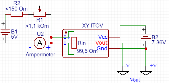
To set up the converter to input the current from a simple serial chain power supply (IP) + resistor. By the law of OHM, if the voltage PI = 5 V, then ^
- For the current 4 Ma will need resistance R = 1.25 Com (nearest 1.2 Kom).
- For current 20 Ma-250 Ohm.
At the same time, consider that at the entrance XY-ITOV, judging by my measurements, stands resistance to 99.5 Ohm. Accordingly, the chain already has resistance ~ 100 Ohm. Therefore, the values of the boundary resistances will be:
Fo 4 Ma-1.15 Com
For 20 Ma-150 Ohm.
Consistently Connect resistor to <150 ом="" и="" прецизионное="" переменное="" сопротивление="">1.2 com.</150> I used a 10-Kom, no other at hand.
- Connected XY-ITOV to a power source ~ 14 V. If The jumpers are exposed to a voltage of up to 10 V, the power source must be 12V.
- Both jumper-and withdrew to the voltage range was 0.. 3.3 V.
- I Connect the ammeter as indicated on the diagram.
- I Connect the multimeter to the Vout and GND terminals and rotate the ZERO potentiometer to display the lower voltage range on the Vout. I exposed 0.66 V for 4 mA current.
- Rotating potentiometer R1 pick up current on Ammeter 20 mA.
- I Connect the multimeter to the Vout terminals and rotate the potentiometer SPAN expose the upper voltage range on the Vout. I exposed 3.3 V for 20 mA current.
- If you remove the connection of the power supply from I-/I +, simulating a breakage of the wire to the sensor, the output will be voltage 0.08 V.
- Current Converter 4.. 20 mA in voltage XY-ITOV calibrated for operation.
- If instead of a power source with a voltage of 7 V use a lower voltage, for the test I used 5 V, the converter shows Vou t = 2.94 V. The calibration does not pass. The Rotation of the SPAN potentiometer does not result in a change in the output voltage. It remains = 2.94 V.
Switching of current converter into voltage to ESP8266
Wemos D1 Mini (ESP8266) is widely represented on Aliexpress at a price of less than 3 USD. Connect the current converter card to the voltage to this microcontroller.
After careful calibration, connect the Earth from the converter to the ND Wemos D1 Mini, and Vout to the stump A0.
Since The converter is 10-bit, the number of levels equals 2 ^ 10 = 1024. In theory, the range of measurement of the voltage ADC ESP8266 from 0 to 1 V. The Manufacturers of boards unpack the additional resistive divider of tension, therefore the data on what voltage supports ADC it is necessary to look at the manufacturer of a board. 🙁 The sources indicate that "Wemos D1 Mini has already build in divider R1 220k/R2 100k for pin A0", so the voltage may vary from 0 to 3.3 V. When calibrated, 20 mA corresponds to 3 V. Upper voltage must meet the value of 1023, because 0 corresponds to 0, and only 1024 level. It is Calculated that L = 1023 * 3/3.3 = 930.
However, if you apply voltage 3 V to the input of analog input, the ADC will display the value of 991, which is significantly different from the theoretical calculation. If to recalculate the upper limit is equal to the value obtained for 3 V, it will be: 991 * 3.3/1023 = 3.196774 V. In General, whether the ADC is so bad, whether there are any other problems.
The Formula for calculating the ADC value in current, I = ADC * 20 (mA)/991, where ADC is the value read from the ADC input.
void Setup () {
    Serial. Begin (115200);
}

void Loop () {
  float ADCR = analogRead (0);
  float val = adcr * 20/991;
  Serial. Print ("ReadADC:" + String (ADCR) + "t");
  Serial. println ("ReadADC, mA: t" + String (val));
  Delay (500);
}
After starting the program we get the following results:
21:21:54.448-> ReadADC: 992.00 ReadADC, mA: 20.02
21:21:54.928-> ReadADC: 991.00 ReadADC, mA: 20.00
21:21:55.441-> ReadADC: 991.00 ReadADC, mA: 20.00
21:21:55.955-> ReadADC: 991.00 ReadADC, mA: 20.00
21:21:56.435-> ReadADC: 991.00 ReadADC, mA: 20.00
21:21:56.951-> ReadADC: 991.00 ReadADC, mA: 20.00
If You disconnect the current source, the ADC shows a zero value. The ADC Bit Capacity is not enough to recognize such a small voltage value. On Zero on ADC It is possible to identify a breakage of a wire.
The DAC can be switched to the voltage measurement of the power supply, in this case the values from the input A0 read pointless.
ADC_MODE (ADC_VCC)//Switch ADC to measuring battery level

float Batterylevel;

void Setup () {
  Serial. Begin (115200);
  Batterylevel = ESP. getVcc ();

  if (batterylevel<= 2170){></= 2170){>
    ESP. deepSleep (0);
  }
}

void Loop ()
{
  Serial. Print ("Battery level is:" + String ((Batterylevel/1000.0)));
}
Switching of current converter into voltage to ESP32
I Connect the Earth from the converter to the (ND) ESP32 DevKit, and Vout to the Stump ADC1_0 (GPIO36). In General, you can migrate the code ESP8266 to ESP32-it will work with a couple of edits: the PIN for reading is not 0, and 36 and correction factor approximately 3350. It's hard to calibrate Exactly. The 12-bit ADC is quite accurate, so the slightest change in input voltage will be read. In addition, the ADC without calibrated reference voltage (reference voltage) will not be able to provide accurate measurements.
void Setup () {
    Serial. Begin (115200);
}

int lastMillis = 0;
void Loop () {
  int currentMillis = Millis ();
  if (currentMillis-lastMillis > 500)
  {
    float ADCR = analogRead (A0);
    float val = adcr * 20/3350;
    Serial. Print ("Read ADC pi[" + String(A0) + "]n:" + String (ADCR) + "t");
    Serial. println ("ReadADC, mA: t" + String (val));
    lastMillis = currentMillis;
  }
}
You can use a different code option to measure the voltage on the ESP32. But in this case the correction factor will be 3850:
#include &lt; driver/ADC. h >
void Setup () {
Serial. Begin (115200);
Adc1_config_width (ADC_WIDTH_BIT_12);
Adc1_config_channel_atten (ADC1_CHANNEL_0, ADC_ATTEN_DB_11);
}
int lastMillis = 0;
void Loop () {
int currentMillis = Millis ();
if (currentMillis-lastMillis > 500)
{
float ADCR = Adc1_get_raw (ADC1_CHANNEL_0);
float val = adcr * 20/3850;
Serial. Print ("Read ADC pi[" + String(A0) + "]n:" + String (ADCR) + "t");
Serial. println ("ReadADC, mA: t" + String (val));
lastMillis = currentMillis;
}
}To smooth the noise in the circuitry ESP32 manufacturer recommends adding a capacity of 0.1 uF to the input ADC, which is involved and use averaging on several counts.
Voltage Converter in current 4.. 20 Ma
On This link it is possible to find the Antiunder previously Rassmrev module, producing the inverse transformation of the voltage in the current 4.. 20 Ma (voltage to current converter). This module, when connected to the voltage sensor, will increase the cable length from it to the microcontroller.
Analogues of current Converters 4.. 20 Ma
If you search on the Internet then converters of current 4.. 20 Ma in the voltage from the brand manufacturers are not cheap, ~ 22 USD. Like this one. It can connect up to 4 sensors, i.e. Price for the sensor in the area of 5 USD. On the board already have 16-digit ADC, it is still about 1.5 USD savings. 🙂
Fritzing part for current to voltage 4.. 20 mA Converter

Not found in the Internet suitable fritzing part for the current Converter 4.. 20 Ma in voltage. So I drew mine. Take it here. Do not forget to like. 🙂
Useful Links
- Work with ADC (ADC) in ESP32 in the documentation from ESPRESSIF (ENG).
- Work with ADC (ADC) in ESP32 in the documentation from NodeMCU (ENG).
- Recommendations on circuitry ESP32 from the manufacturer. Pay attention to the VDDA-analog power supply-the reference voltage for ADC.
- Example of working with ADC ESP32 (ENG).
- Working with ADC in ESP8266 (Eng).
- ADC in ESP8266 (Eng).
- Discussion of the maximum voltage of ADC ESP8266 (ENG).
- Discussion of how to use ADC ESP8266 (RUS).
- Discussion of the accuracy of ADC ESP32 (ENG).