Arduino Has A significant number of entries in the older versions (Arduino Mega), but the device itself is still more sharpened for prototyping and releasing IoT devices in small quantities. Quickly and cheaply to shut the gap. This option is not suitable for all tasks, especially when you need to deploy hundreds of IoT devices.
On Arduino is quite convenient to develop. There is a Aruino IDE, a simple C++ version, support in the Visual Studio Code/Visual Studio 2017 environment. Huge expertise, a lot of staff libraries, covering many tasks, mass of forums, articles, etc. are Accumulated. However, unfortunately, if you need to do a remote firmware update, the normal staffing solution for Arduino I could not find. Non-Standard bootloader have been developed for a long time, no code updates and how stable work is unclear.
ESP8266 Microcontrollers and senior fellow ESP32 are industrial microcontrollers, well documented with regular support for software updates over TCP/IP.
If you are developing a solution for industrial automation, I recommend using ESP chips. It Will be a good future in terms of further development. Given that the code under ESP can be created on C++ in the Arduino IDE/Visual Studio Code/2017, and many libraries are compatible between Arduino and ESP, you can switch from ESP to Arduino if necessary. Of Course, with the loss of the functionality of Wi-Fi, which is built into ESP, and Arduino requires additional shield. For example, the same ESP8266. 🙂
The ESP chips already have Wi-Fi and Bluetooth (ESP32) support, low power modes, which simplifies the development of battery-powered devices.
Power Supply ESP8266/ESP32
For Standalone power supply recommend using a capacious Li-Ion battery 18650. On Aliexpress You can find battery options for 9900 mAh. Most likely the Chinese are cunning, putting this figure, but the battery is really capacious.
It is easy To find inexpensive battery shield to power devices on these microcontrollers. There is also a low-cost passive battery case for the case when the Li-Ion battery is operated on a separate shield. For Example, the Wemos D1 Mini Board has this shield option.
ESP8266 vs ESP32
In Short I will compare ESP8266 with ESP32.
ESP8266 | ESP32 | |
|---|---|---|
Mcu | Xtensa Single-Core 32-bit L106 | Xtensa Dual-Core 32-bit LX6 with 600 DMIPS |
802.11 b/g/n Wi-Fi | HT20 | HT40 |
Bluetooth | X | Bluetooth 4.2 and BLE |
Typical Frequency | 80 MHz | 160 MHz |
Sram | X | ✓ |
Flash | X | ✓ |
Gpio | 17 | 36 |
Hardware/Offware PWM | None/8 Channels | None/16 Channels |
SPI/I2C/I2S/UART | 2/1/2/2 | 4/2/2/2 |
Adc | 10-bit | 12-bit |
CAN | X | ✓ |
Ethernet MAC Interface | X | ✓ |
Touch Sensor | X | ✓ |
Temperature Sensor | X | ✓ |
Hall Effect Sensor | X | ✓ |
Working Temperature | -40 º C to 125 º C | -40 º C to 125 º C |
Price | US $ ($3-$6) | $ $ ($6-$12) |
Where to buy |
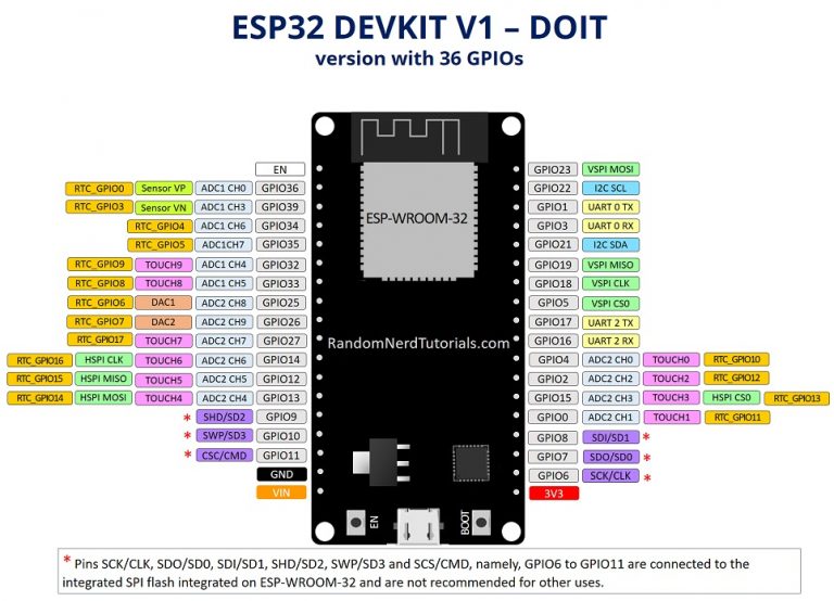
You can Use GPIO inputs/outputs on these chips in different ways.
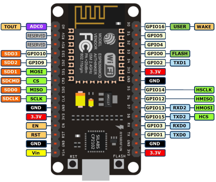
When purchasing ESP32 Devkit on Aliexpress you need to pay attention to the number of PINS. The Most common version is 30 PIN, the same as ESP8266. It is in the area of 5 USD. There is an option on 36 PIN and 38 PIN. On 38 The PIN stands in the area of 8 USD. It is easy to Distinguish, PIN-s are lowered to the bottom edge of buttons.
Here it is necessary to look, that it is necessary from a payment as it is possible to be more profitable to buy expansion on 16 GPIO for 1.5 USD, than to overpay for PIN-S on Devkit.
ESP32 has a number of sensors that can be used in the development of simple solutions. For Example, you can periodically poll the temperature sensor to monitor the health status of the chip itself to prevent it from overheating.
ESP32 can use 10 inputs as capacitive (TOUCH). The wire Attached to them will change the capacity of the hand. For Example, you can implement timeless capacitive buttons that can be implemented on the PCB, without the use of a mechanical component.
Increasing the number of analog inputs/outputs
Analog-to-digital converter ADC (ADC)
In ESP8266 There is only one ADC (ADC), while the ESP32 is available 18!!! ADC, and 12 bit, in contrast to the 10-bit ADC ESP8266. The Voltage of the ADC in ESP32 can be changed from 0 to 4 V.
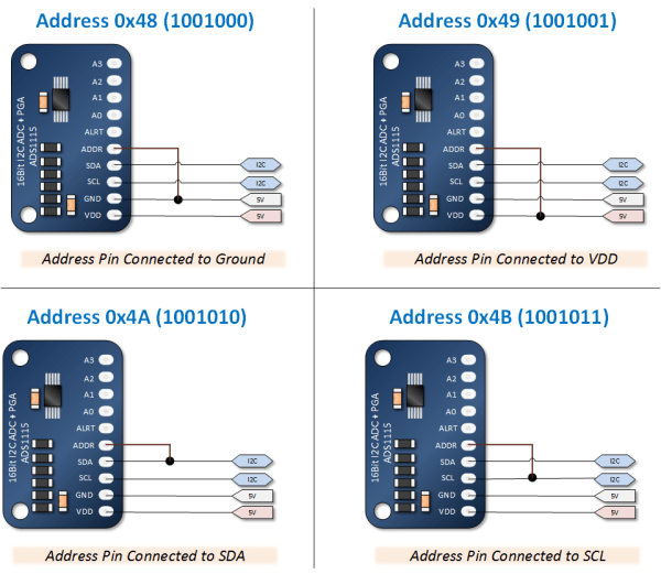
16-bit external modules of ADC with Chip ADS1115 4-channel and cost with delivery to Russia in the area of 1.5 USD. About the same cost 12-bit ADS1015. Datasheet here.
In ESP8266 To get the same number of channels ADC, as ESP32 will need 4 pcs. External ADC and the price of these modules will be in the area of 6 USD. The chip ESP32 split on the board can be purchased for about 7 USD with delivery to Russia. The wiring Diagram is here.
If There is a doubt about the input voltage, it is advisable to use an external ADC, because the failure of the circuit board on 4 channels will cost a bit cheaper than the loss of the microcontroller. Or to insure the installation of Stabilitron.
- 4-channel 18-bit ADC MCP3424 will cost about 5 USD. Junior single-channel brother MCP3421 in about 2.5 USD.
- 2-Channel 24-bit ADC ADS1232 will cost about 4 USD. There is a 4-channel version of ADS1234, but the card with this chip is absent on Aliexpress. Only the chip is Available.
- 24-bit ADC ADS 1256 will be already 8-channel, small savings, but the price in the area of 15 USD for the quality of digitization.
- 24-bit ADC for digital weights HX711 will cost less than 2 USD.
- 3-Channel 24-bit ADC AD7793 will cost about 7 USD. Datasheet here.
In Addition to ADC in ESP32 there are two 8-bit DAC (DAC).
Multiplexer/demultiplexer Analog inputs
In Addition to increasing analog inputs using ADC, there is an option to extend the multiplexer. A Good article on this topic in which the analog multiplexer/demultiplexer CD4051/74HC4051 is considered in detail. Many options from other manufacturers.
CD4051 is an 8 channel analog CMOS multiplexer/demultiplexer. To increase the number of analog inputs by 7, 1 analog and 3 digital inputs are required.
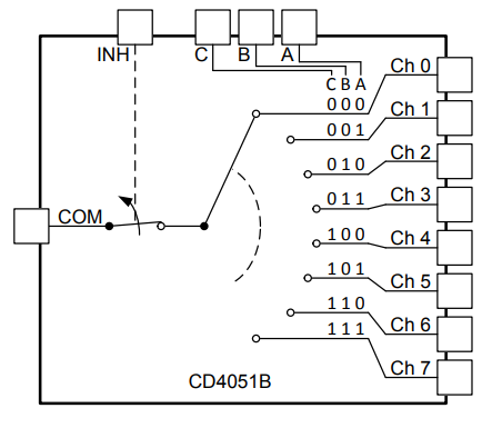
The Multiplexer transmits a signal from one of several inputs to a single output. Demultiplexer, on the other hand, transmits a signal from a single input to one of the information outputs.
If you buy a module on Aliexpress, the price will be in the area of 0.8 USD for 8 channels, 16-bit ADC ADS1115-1.5 USD for 4 channels. If you buy only the chip CD4051, the price will be much lower than the ADC chip.
Increased number of digital GPIO inputs/outputs

To increase the number of digital inputs, you can use the good-quality GPIO Extender card for 8 Inputs/Outputs. It is well documented, performed at a high technical level. Although, the price tag is not Aliexpress. 🙂 In the manufacture of several hundred devices, the cost of the target device will grow significantly.
Let's see what the Chinese fellows have on this account. And They certainly have something to eat and inexpensive. 🙂

8-channel GPIO Extender on PCF8574 chip with DIP switches to assign I2C address
Immediately Note the quality performance of modules at a price in the area of 1 USD. The Chip from TI PCF8574 provides 8 I/O channels (GPIO) controlled by the I2C bus. There is an INT output connected to the microcontroller input that supports interrupt processing. If an interrupt occurs on one of the inputs of the expansion card, the interrupt is broadcast to the microcontroller for further priority processing of the incoming signal.
Structurally, the blue modules are comfortable to cascade, sticking one in the other. The Address of the devices is conveniently set by either DIP switches or Jamperami. It is Possible to connect internal pullup resistors on + 5V.
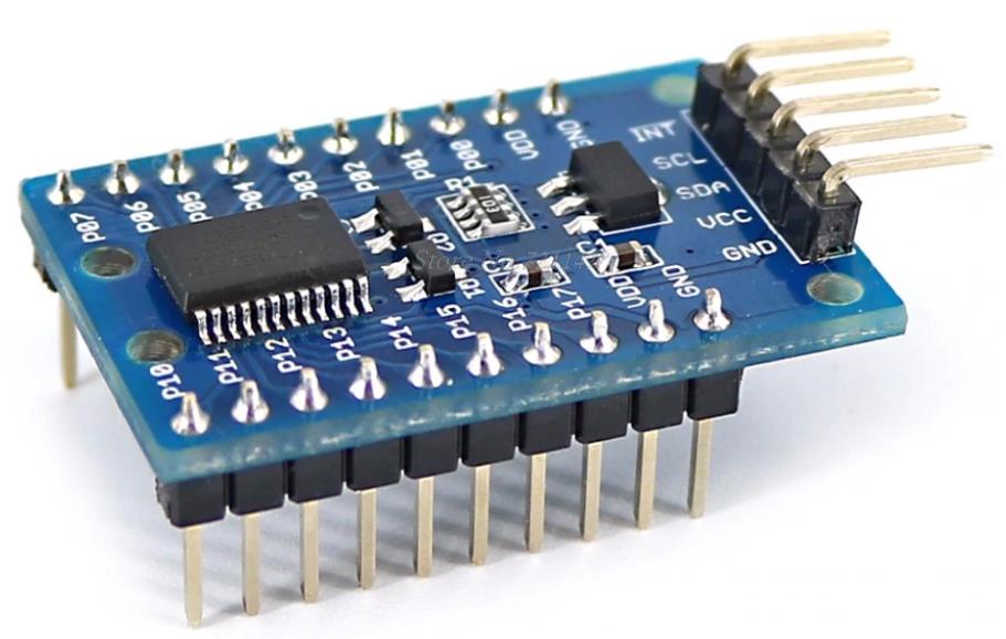
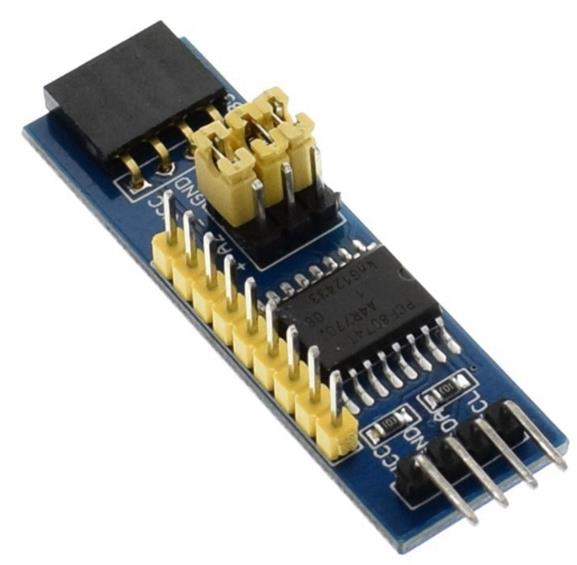
16-channel GPIO extender on Chip PCF8575
The Older brother TI PCF8575 allows you to get 16 GPIO ports for a price of two times higher. But the implementation of the Board is simpler. No DIP switches to select the address I2C. But 16 channels in a compact version.
A Similar chip from the company Microchip to expand the number of GPIO ports, MCP23017. There is an option for the I2C bus and more nimble for SPI (MCP23S17). Chinese sellers often indicate in the description of the product chip MCP23S17, but the photo board shows that the chip MCP23017. Pay attention to this!
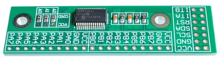
The Price of this version of the module in the area 1.5 USD. The Performance of the board is almost twice as cheap. The Chip allows you to increase the GPIO by 8 + 8 = 16. Like the chip from Texas Instruments in addition to the inputs to connect devices there are two interrupt outputs on each block of 8 devices. This chip allows to operate at a frequency up to 1.7 Mhz and 10 MHz for the version under the SPI bus, unlike the chip PCF8574 for which the upper limit 400 Khz. It is Also possible to connect internal pullup resistors to + 5V. The Scheme of connecting the board to ESP8266 disassembled here.
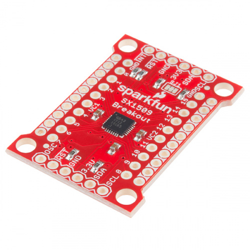
Another 8 + 8 = 16-Channel Extender number GPIO with Aliexpress chip SX1509. Library and description from Sparkfun. The Chip is more expensive than the previously presented. According to the TTH chip is very similar to the previously considered options. Operates at a frequency of 400 Khz. There is built-in support for PWM (PWM) on outputs.
Chip "sharpened" to work with LED and keyboard. In part LED because of the presence of PWM allows you to control the brightness of the lights, perform fading, blinking, etc. There is an INT output to broadcast interrupts to the microcontroller. Built-in pull-up, pull-down resistors on inputs are Supported.
Rtc
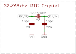
On one RTC articles in ESP32-it is not Real Time Clock, and the kernel of low power consumption. However, the other is still Real Time Clock, but of poor quality (+-5%), which is not worth using in business applications.
Perhaps the problem of inaccuracy of the built-in RTC can be solved by adding an external quartz resonator. I found a reference to the connection scheme of the Carcate resonator to the contacts RTC_GPIO8/RTC_GPIO9.
In General, not the fact that you can save on the entrance. 🙁 Especially If you need data logger, not just RTC. In Data Logger RTC is already embedded and SPI conclusions on read/write will have to give:-(. Although in Data logger RTC is often connected to the I2C bus.
Connection of Sensors 4.. 20 Ma
Considered in the article.
Connecting I2C Sensors
In theory, up to 127 devices can be connected to a single I2C bus. Each device must have its own unique address. Often the address of the device one and rigidly "pro", therefore it is impossible to connect on one bus some such modules. Inputs I2C in ESP only 1 (2 y ESP32) PCs.
I2C multiplexers are used To connect I2C devices with matching addresses. On Aliexpress from inexpensive available I2C extender on chip TCA9548A. Price in the area of 1 USD with delivery to Russia.
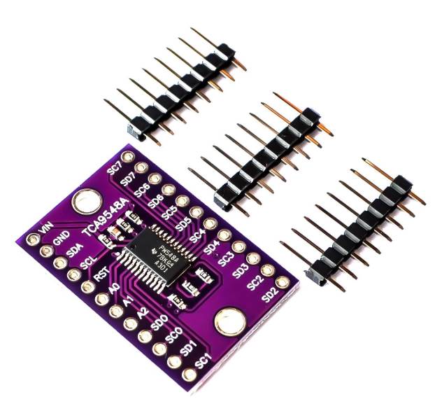
The Multiplexer works simply. By default, it is assigned a certain address. The Microcontroller connects to it on the I2C bus and then sends a command to select one of the 8 outputs with which the communication will take place. You can Then interact with the I2C device as if it had a direct connection. If it is necessary to periodically poll all sensors connected to 8 entrances, such poll occurs in a cycle.
In Fact, the multiplexer provides a temporary direct commutation of the GPIO microcontroller with the selected device by its number. This is some inexpensive workaround to solve problems with the I2C address conflict.
RS485 Interface

A Detailed overview of the leisure modules implementing the RS485 interface is made in the article.
K-Type thermocouple Connection
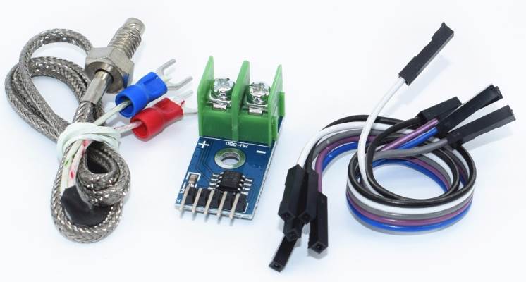
he microcontroller on the SPI bus
Connection of Thermocouple to ESP32/ESP8266/Arduino with the help of modules MAX6675 and MAX31855.
Increase in the number of UART (RX/TX) ports
For some tasks, there is a need to increase The number of serial ports. For older Arduino models, such as Mega, there is no need to increase serial ports, there are enough of them. However for ESP8266 The problem is quite actual, considering that there is only one hardware serial port, and that is often occupied under the broken-down on a board USB a carpet-cutter. You can emulate the serial port operation on GPIO using SoftSerial, but not all tasks are acceptable.
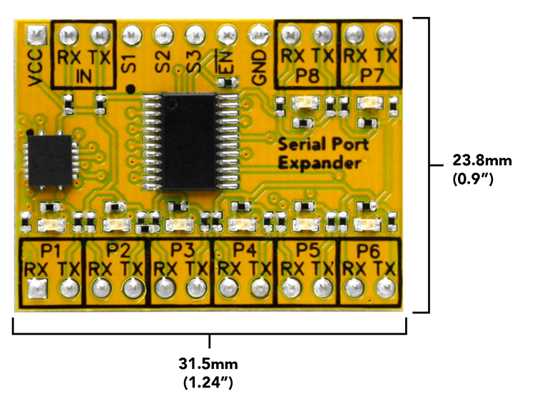
) on 8-th additional serial ports
The Decision from the company AtlasScientific-8:1 Serial Port Expander is the most expensive. The Price in the area of $15 without delivery is quite high, although compared with one and two port modules, the price for the port is less than $2, which is more advantageous than the 1-2 port counterparts.

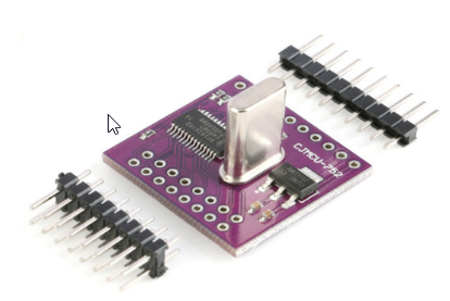
SC16IS760 module for converting I2C/SPI to one UART port
There are converters I2C in one port UART and 8 GPIO ports on the chip SC16IS750. It Costs about $4 with leaving to Russia. SPI option on the chip
SC16IS760. Considering that on one bus it is possible to hang several modules-it is possible to dial the necessary quantity. SPI Port is quite nimble enough to ensure the connection of a large number of such modules.
There is a senior colleague of I2C in two ports UART and 8 GPIO ports on the chip SC16IS752. Cost about $5. SPI option on the chip SC16IS762.
Boards on Chips MAX14830, MAX3107, MAX3108, MAX3109 I have not found on Aliexpress.
Schematic solution for obtaining 4 ports UART.
Conclusion
This is a brief overview of the options for extending microcontroller inputs. In the future I will discuss the work with the specified modules in detail.